What are Analog Circuits?
Electronics and Communication Engineering
What are Analog Circuits?
Analog Circuits form one of the fundamental pillars of Electronics and Electrical Engineering. They deal with analog signals, which are continuous signals that vary smoothly with time and represent real-world physical quantities such as light, sound, temperature, and pressure. Unlike digital signals that operate in discrete levels, analog signals change continuously, making them essential for real-life sensing, communication, and control systems.
Working Principle of Analog Circuits and Real-World Applications
In practical terms, analog circuits operate with continuously varying voltages and currents. When you speak into a microphone, your voice is converted into a continuously varying electrical signal. This signal is then processed using amplifiers, filters, and other analog components such as diodes, BJTs, MOSFETs, resistors, and capacitors. From communication systems and power electronics to instrumentation and embedded applications, analog circuits remain the backbone of modern electronic systems.
Importance of Analog Circuits in GATE, ESE, PSU, and SES Exams
From a competitive exam perspective, Analog Circuits hold significant importance in GATE, ESE, PSU, and State Engineering Services (SES) examinations. Questions are often conceptual and application-oriented, covering topics such as diode circuits, BJT and MOSFET analysis, amplifiers, small-signal models, frequency response and feedback systems. With strong fundamentals and systematic practice, this subject becomes highly scoring.
Master Analog Circuits with Structured Guidance from MADE EASY
At MADE EASY, we believe that conceptual clarity is the key to mastering Analog Circuits. Our structured teaching methodology, detailed theory coverage, and exam-oriented problem-solving approach help aspirants build a strong foundation and improve accuracy in GATE, ESE, PSUs and other competitive examinations. With the right guidance and consistent effort, Analog Circuits can become one of the strongest areas in your preparation.
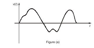
The voltage signal shown in the figure below is called an analog signal. The name derives from the fact that such a signal is analogous to the physical signal it represents. The magnitude of an analog signal can take any value; that is, the amplitude of an analog signal exhibits a continuous variation over its range of activity. Electronic circuits that process such signals are known as analog circuits.
Given below are some links to important topics that will help you understand analog circuits:
Key Concepts:
Overview of Analog Circuits
Analog circuits are electronic circuits that process signals by transmitting continuous voltage or current. They are made up of passive components like resistors, capacitors, and inductors, as well as semiconductor devices like diodes and transistors. Devices such as diodes, BJT, and rectifiers are some of the very important devices used in analog electronics circuits. Let us learn some basics about them.
Diodes
The simplest and most fundamental non-linear circuit element is diode. Just like a resistor, the diode has two terminals; but unlike the resistor which has linear (straight-line) relationships between the current flowing through it and the voltage appearing across it, the diode has non-linear i-v characteristics.
The positive terminal of diode is called anode and the negative terminal is cathode. If a negative voltage is applied to the diode, no current flows and the diode behaves as an open circuit. Diodes operated in this mode are said to be reversed biased. On the other hand, if a positive current is applied to the ideal diode, zero voltage drop appears across the diode. In other words the ideal diode behaves as a short circuit in the forward direction. Diodes operated in this mode are said to be forward biased.
Bipolar Junction Transistors
Three terminal devices are far more useful than two terminal ones, such as diodes studied above, because they can be used in multiple applications, ranging from signal amplification to designing of digital logic and memory circuits. The basic principle involved is the use of the voltage between two terminals to control the current flowing in the third terminal. In this way, a three terminal device can be used to realize a controlled source, which is necessary for amplifier design. Also, in extreme cases, the control signal can be used to cause current in the third terminal to change from zero to larger value, thus allowing the devices to act as a switch.
The transistor consists of two pn- junctions, the emitter-base junction (EBJ) and the collector-base junction (CBJ). Depending on the bias condition (forward or reverse) of each of these junctions, different modes of operation of BJT are obtained, as shown in Table.
| S. No | Mode | EBJ | CBJ | Properties | Applications |
|---|---|---|---|---|---|
| 1 | Cut-off | Reverse bias | Reverse bias | Very high internal resistance | OFF switch |
| 2 | Active | Forward bias | Reverse bias | Excellent transistor action | Amplifier |
| 3 | Saturation | Forward bias | Forward bias | Very low internal resistance | ON switch |
| 4 | Reverse active | Reverse bias | Forward bias | Very poor transistor action | Attenuator (Practically not used) |
Mode refers to the way how junctions of BJT are biased.
Rectifier
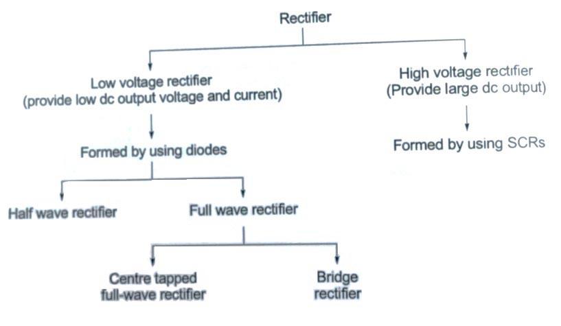
A rectifier that converts an AC voltage to a unidirectional voltage is used as a DC supply for many electronic circuits, such as those in radios, calculators, and stereo amplifiers. A rectifier is also called an AC-DC converter, rectifiers can be classified on the basis of AC supply into two types: single phase rectifiers and three phase rectifiers. Three phase rectifiers are normally used in higher power applications; are outside the scope of this book. The following single phase rectifiers are commonly used in electronic circuits:
- Single phase half wave rectifiers.
- Single phase full wave center tapped rectifiers.
- Single phase full wave bridge rectifiers.
Advantages of Analog Circuits
- The majority of signals in the “real world” are analog; so these signals can be directly processed in analog circuits whereas digital processing requires analog to digital and digital to analog conversion.
- Analog circuits can be designed to operate even at higher power levels.
Disadvantages of Analog Circuits
- Loss of information due to the effect of noise is more.
- Lower quality signals than digital signals.
Online Courses for Analog Circuits (EC):
A bachelor’s or master’s degree is an eligibility criteria to pursue a successful career in electrical and communication engineering. But having a strong grasp on key topics and subjects is a very important aspect. Particularly, students preparing for government engineering exams may encounter intense competition. And MADE EASY Courses with the renowned experts are here to provide guidance and support during your preparation journey for GATE, ESE, and PSU exams. The courses focus on providing quality lectures from the basic level to the advanced level. MADE EASY provides aspirants with the right guidance to maximize their performance and achieve success. Electronics and communication engineering candidates are advised to visit the links given below to learn more about courses that include key concepts of engineering branches taught at the basic level and prepare aspirants for the future.
- ESE+GATE 2026 – 27 Live Online Foundation Course
- GATE 2026 Live Online Foundation Course
- Tablet Course for GATE 2026 – 27
- GATE + ESE 2026 – 27 Online Recorded Course
Recommended Books for Analog Circuits
Books are still an essential part of learning as they offer in-depth knowledge in various topics. Learning books are well structured and provide comprehensive understanding making them invaluable for students and lifelong learners. MADE EASY Publications is one such platform for students who are looking for high quality and well-structured content for their preparation. Our platform consists of government engineering exams books which are curated by a team of experts and experienced authors. EC engineering aspirants are suggested to click on the links mentioned below to learn more in depth about analog circuits:
- A Handbook on Electronics Engineering
- GATE-2026: Electronics Engineering Previous Year Solved Papers
- 4000 MCQ : Electronics Engineering
- A Text Book on Analog Electronics: EE/EandT/IN
MADE EASY faculty have briefly explained analog circuits and the other key concepts. Click on the given links to learn more about environmental engineering.
▶️ Digital Electronics | EE +EC | By Ramesh Sir | MADE EASY
▶️ Opamp with Positive Feedback | Analog Circuits
Dear Aspirants,
Your preparation for GATE, ESE, PSUs, and AE/JE is now smarter than ever — thanks to the MADE EASY YouTube channel.
This is not just a channel, but a complete strategy for success, where you get toppers strategies, PYQ–GTQ discussions, current affairs updates, and important job-related information, all delivered by the country’s best teachers and industry experts.
If you also want to stay one step ahead in the race to success, subscribe to MADE EASY on YouTube and stay connected with us on social media.
MADE EASY — where preparation happens with confidence.
MADE EASY is a well-organized institute, complete in all aspects, and provides quality guidance for both written and personality tests. MADE EASY has produced top-ranked students in ESE, GATE, and various public sector exams. The publishing team regularly writes exam-related blogs based on conversations with the faculty, helping students prepare effectively for their exams.