
What are logic gates? Definition, Types and Uses
What are Logic Gates?
Logic gates are electronic circuits that make logical decisions. Logic gates, in their physical form, are typically found within LSI (Large-Scale Integration) and VLSI (Very Large-Scale Integration) circuits, which also contain many other components. Logic gates allow computers to make logical choices. When using a logic gate, binary numbers (1s and 0s) are used as inputs, and by applying different rules, the logic gate produces an output that is a single number. Every output and input utilized by a logic gate will be one of two different values (False = Low = 0, True = High = 1).
Logic gates are composed of at least two inputs, with the exception of the NOT gate, which has only one input. A truth table can be created to define the relationship between the inputs of each logic gate and its corresponding output.
All of the functions performed by a logical gate can be described using Boolean algebra.
Types of Logic Gates
Logic gates are classified into 3 categories:
- Basic logic gates
- Universal logic gates
- Special-purpose logic gates
Let us look at each category one by one.
Basic logic gates
Basic logic gates are the simplest logic gates which perform basic operations. Every other logic gate is build using these logic gates only.
The three basic logic gates are: NOT, AND, OR.
- NOT Gate: Known as the “inverter,” the NOT gate performs the inversion or complementation function. It has a single input and a single output. The output logic level of a NOT gate is always opposite to the logic level of the input, i.e., when a HIGH level is applied as an input, the inverter shows a LOW level at its output and vice versa. The symbol of the NOT operation is represented by the symbol (—) (bar). Therefore, for any input A, the output of the NOT gate is A.
The symbol of NOT gate is given below:

The truth table for NOT gate is
| Input | Output |
|---|---|
| 0 | 1 |
| 1 | 0 |
The switching circuit and transistor circuit is given below.
For the switching circuit

When,
- Switch K is open, i.e. logic ‘0’ then, bulb glows (shows logic 1).
- Switch K is closed, i.e. logic ‘1’ then, bulb does not glows (shows logic 0)
Similarly, for the transistor circuit
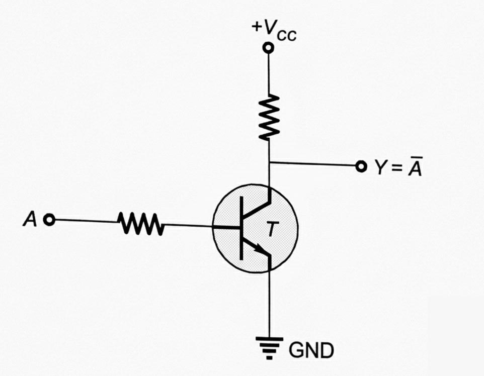
When,
- A=0; T=Off and Y=+Vcc
- A=1; T=On; and Y=Ground
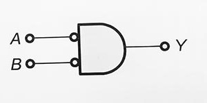
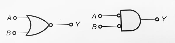
AND Gate: An AND gate can have two or more inputs but only one output. The output of AND gate is HIGH if both of the inputs are HIGH and LOW if anyone of the input is LOW. The logic symbol of AND gate is given below.
The truth table of AND gate is given below:
| Input | Output | |
|---|---|---|
| A | B | Y |
| 0 | 0 | 0 |
| 0 | 1 | 0 |
| 1 | 0 | 0 |
| 1 | 1 | 1 |
The logical expression of AND gate is
AND Gate follows both commutative and associative law as:
- Commutative law: AB = BA
- Associative law: ABC=(AB)C=A(BC)
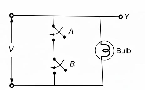
The switching circuit diagram for the AND gate is shown below:

The bulb will glow only when both the switches A and B are closed or at logic “1.”
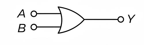
OR Gate : OR gate can have two or more inputs but only one output. The output of AND gate is HIGH if any one of the inputs is HIGH and LOW if both of the input is LOW. The logic symbol of OR gate is given below.
The truth table of OR gate is given below:
| Input | Output | |
|---|---|---|
| A | B | Y |
| 0 | 0 | 0 |
| 0 | 1 | 1 |
| 1 | 0 | 1 |
| 1 | 1 | 1 |
The logical expression of OR gate is Y=A+B
AND Gate follows both commutative and associative law as:
- Commutative law: A+B=B+A
- Associative law: A+B+C=(A+B)+C=A+(B+C)
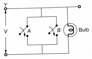
The switching circuit diagram for AND gate is shown below:
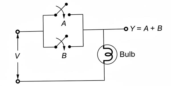
The bulb will glow only when any of the switch (either A or B) are closed or at logic “1”.
Universal logic gates
Those logic gates which can perform all the three basic function of AND, OR and NOT gates are called Universal logic gate. NAND gate and NOR gate are called universal gate.
- NAND Gate: NAND Gate is the combination of AND gate followed by NOT gate. Therefore, the working of NAND gate is NOT-AND operation. NAND gate may have two or more input but only one output. The output of NAND gate is LOW when both the inputs are HIGH otherwise for any other case, the output of NAND gate is HIGH.
The logic symbol of NAND Gate is given below:

The truth table of NAND gate is given below:
| Input | Output | |
|---|---|---|
| A | B | Y |
| 0 | 0 | 1 |
| 0 | 1 | 1 |
| 1 | 0 | 1 |
| 1 | 1 | 0 |
The logical expression for the output of NAND Gate is Y=A ̅+ B ̅=(A.B) ̅
The NAND Gate is also called active LOW OR gate.
NAND Gate follows only commutative but not associative law as:
- Commutative law: (A.B) ̅=(B.A) ̅
- Associative law: (ABC) ̅=A ̅+B ̅+C ̅
The switching circuit diagram for NAND gate is given below.
The bulb will glow when any one of the switch (A or B) is open.
- NOR Gate: NOR Gate is the combination of OR gate and NOT gate. Therefore, the working of NOR gate is NOT-OR operation. NOR gate may have two or more input but only one output. The output of NAND gate is LOW when any one or both of the inputs is HIGH, if both the inputs are LOW, then the output of AND gate is HIGH.
The logic symbol of NOR Gate is given below:
The truth table of NOR gate is given below:
| Input | Output | |
|---|---|---|
| A | B | Y |
| 0 | 0 | 1 |
| 0 | 1 | 0 |
| 1 | 0 | 0 |
| 1 | 1 | 0 |
The logical expression for the output of NOR Gate is Y=A ̅ B ̅=(A+B) ̅
The NOR Gate is also called active LOW AND gate.
NOR Gate follows only commutative but not associative law as:
- Commutative law: (A+B) ̅=(B+A) ̅
- Associative law: (A+B+C) ̅=(ABC) ̅
The switching circuit diagram for NOR gate is given below.
The bulb will not glow if any of the switch (A or B) is closed.
Special Purpose Logic Gate: EX-OR (Exclusive-OR) and EX-NOR (Exclusive-NOR) gates are called special purpose logic gates.
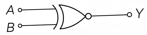
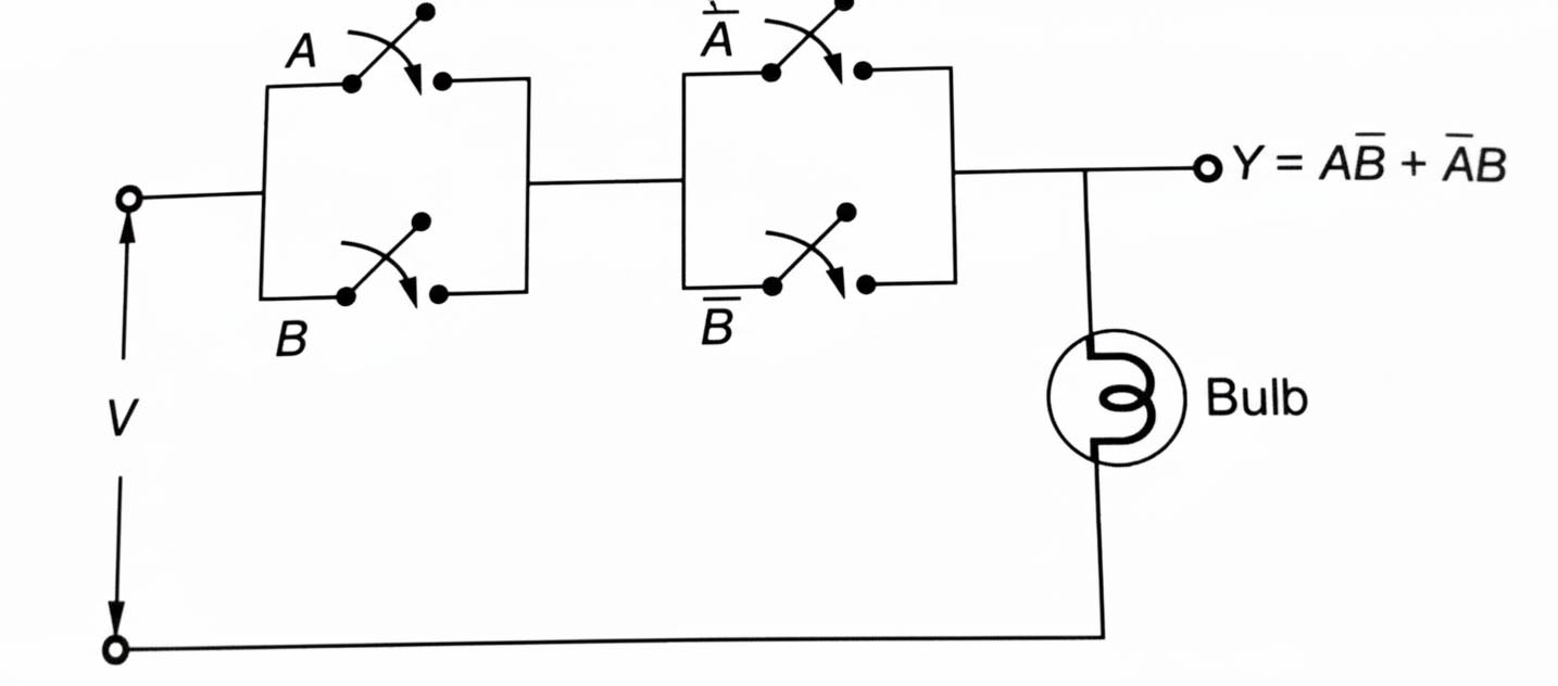
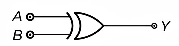
- Exclusive-OR Gate (EX-OR) : EX-OR gate has two input and single output. The output of EX-OR gate is HIGH when only one input is HIGH or, the output is HIGH when both the inputs are different.
The logic symbol of EX-OR Gate is given below:
The truth table of EX-OR gate is given below:
| Input | Output | |
|---|---|---|
| A | B | Y |
| 0 | 0 | 0 |
| 0 | 1 | 1 |
| 1 | 0 | 1 |
| 1 | 1 | 0 |
EX-OR gate is used in “parity generation and detection”. It is also known as “stair case switch”.
EX-OR Gate follows both commutative and associative law as:
The switching circuit diagram for EX-OR gate is given below.
- Exclusive-NOR Gate (EX-NOR) : EX-NOR gate has two input and single output. The output of EX-NOR gate is HIGH when both the inputs are same.
The logic symbol of EX-OR Gate is given below:
The truth table of EX-OR gate is given below:
| Input | Output | |
|---|---|---|
| A | B | Y |
| 0 | 0 | 1 |
| 0 | 1 | 0 |
| 1 | 0 | 0 |
| 1 | 1 | 1 |
EX-NOR gate is also called “gate of equivalence” or “coincidence logic”.
EX-OR Gate follows both commutative and associative law as:
The switching circuit diagram for EX-OR gate is given below.

Logic Gates for GATE
Logic gates are one of the highly important topics for GATE EE, EC, CSE/IT aspirants. Complete and thorough knowledge of logic gates is helpful in understanding various concepts.
Candidates preparing for GATE exam can visit MADE EASY website to know about relevant courses for different streams.
FAQs:
1. Why are logic gates important?
Answer: Logic Gates are important because they help in understanding various process in digital electronics. They are the basics of all digital system.
2. What is a truth table in logic gates?
Answer: Truth table in logic gates represent the relation between input and output for different logic gates.
3. Which logic gates are called universal gates?
Answer: NAND and NOR gate are universal gates.
4. What is the basic logic gate?
Answer: NOT, AND, OR gates are basic logic gate.
5. Are logic gates part of digital electronics?
Answer: Yes, logic gate are part of digital electronics.
Dear Aspirants,
Your preparation for GATE, ESE, PSUs, and AE/JE is now smarter than ever — thanks to the MADE EASY YouTube channel.
This is not just a channel, but a complete strategy for success, where you get toppers strategies, PYQ–GTQ discussions, current affairs updates, and important job-related information, all delivered by the country’s best teachers and industry experts.
If you also want to stay one step ahead in the race to success, subscribe to MADE EASY on YouTube and stay connected with us on social media.
MADE EASY — where preparation happens with confidence.
MADE EASY is a well-organized institute, complete in all aspects, and provides quality guidance for both written and personality tests. MADE EASY has produced top-ranked students in ESE, GATE, and various public sector exams. The publishing team regularly writes exam-related blogs based on conversations with the faculty, helping students prepare effectively for their exams.
