Halfwave Rectifier
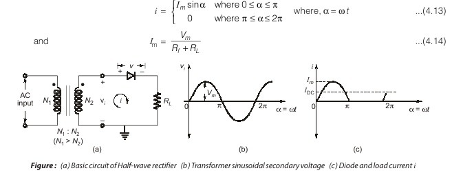
The basic circuit for half-wave rectification is shown in Figure (a). We can assume that the diode has essentially infinite resistance in the reverse direction (for a voltage v less than the cut-in voltage Vγ) and a small and constant resistance Rf in the forward direction (for v > Vγ). Since in a rectifier circuit the input vi = Vm sinωt has a peak value Vm which is very large compared with the offset voltage Vγ, we assume in the following discussion that Vγ = 0. Subject to this idealization of the diode characteristic, the current i in the diode or load (RL) is given by
Dear Aspirants,
Your preparation for GATE, ESE, PSUs, and AE/JE is now smarter than ever — thanks to the MADE EASY YouTube channel.
This is not just a channel, but a complete strategy for success, where you get toppers strategies, PYQ–GTQ discussions, current affairs updates, and important job-related information, all delivered by the country’s best teachers and industry experts.
If you also want to stay one step ahead in the race to success, subscribe to MADE EASY on YouTube and stay connected with us on social media.
MADE EASY — where preparation happens with confidence.
MADE EASY is a well-organized institute, complete in all aspects, and provides quality guidance for both written and personality tests. MADE EASY has produced top-ranked students in ESE, GATE, and various public sector exams. The publishing team regularly writes exam-related blogs based on conversations with the faculty, helping students prepare effectively for their exams.
