STRAIGHT LINE MECHANISMS
A mechanism built in such a manner that a particular point in it is constrained to trace a straight line path within the possible limits of motion, is known as a straight line motion mechanism.
Straight line motion can be generated by either sliding pairs or turning pairs. Sliding pairs are bulky and gets
worn out rapidly. Therefore, turning pairs are preferred over sliding pairs for generating straight line motion. Straight line motion can be generated either accurately or approximately.
Exact Straight Line Mechanisms
- Peaucellier Mechanism
- Hart Mechanism
- Scott – Russel Mechanism
Approximate Straight Line Mechanisms
- Grasshopper mechanism
- Watt mechanism
- Tchebicheff Mechanism
- Robert’s Mechanism
INTERMITTENT MOTION MECHANISM
Intermittent motion is a sequence of motions and dwells. A dwell is a period in which the output link remains stationary while the input link continues to move. Intermittent motion mechanism are used to convert continuous motion into intermittent motion. The mechanisms used for this purpose are the Geneva wheel and the ratchet
mechanism.
Geneva Wheel / Geneva Mechanism
The Geneva mechanism is shown in Fig. The input crank is typically a motor driven at a constant speed. The Geneva wheel is fitted with at least three equispaced, radial slots. 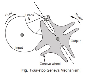
The mechanism shown here is having four slots. The crank has a pin that enters a radial slot and causes the Geneva wheel to turn through a portion of a revolution. When the point leaves that slot, the Geneva wheel remains stationary until the pin enters the next slot. This results in the intermittent motion of the Geneva wheel. The crank is also fitted with an arc segment, which engages a matching cutout on the periphery of the Geneva wheel when the pin is out of the slot. This keeps the Geneva wheel stationary and in the proper location for the next entry of the pin. The number of slots determine the number of “stops” of the mechanisms where stop is synonymous with dwell. The slot provided must be tangential to the path of pin while engaging with the pin to reduce shock and jerk.
Ratchet and Pawl Mechanism
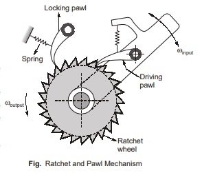
Fig. shows a Ratchet and Pawl mechanism. The arm pivots about the centre of the toothed ratchet wheel and is moved back and forth to index the wheel. The driving pawl rotates the ratchet wheel (or ratchet) in the counter clockwise direction and does no work on the return (clockwise) trip. The locking pawl prevents the ratchet from reversing direction while the driving pawl returns. Both pawls are usually spring-locked against the ratchet. The mechanism is widely used in devices such as “ratchet” wrenches, winches etc.
Davis Steering Mechanism
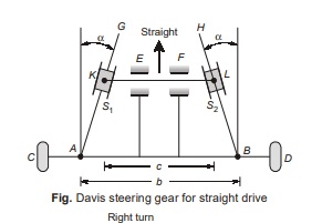
Davis steering gear is shown in Fig. This type of gear has only sliding pairs. Two arms AG and BH are fixed to the stub axles AC and BD respectively. CAG and DBH form two similar bell – crank levers pivoted at A and B respectively. KL is a cross-link which is constrained to slide parallel to AB. The ends of the cross-link KL are pin-jointed to two sliders S1 and S2 as shown in Fig. These sliders are free to slide on links AG and BH respectively. The whole mechanism is in front of the front wheels.
During the straight motion of the vehicle, the gear is in the mid-position, with equal inclination of the arms AG and BH with the verticals at A and B. The steering is achieved by moving cross-link KL to the right or left of the mid-position. The steering gear for taking a right turn is shown in Fig. (below). K‘L’ shows the position of the crosslink KL while taking a right turn.
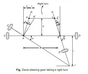
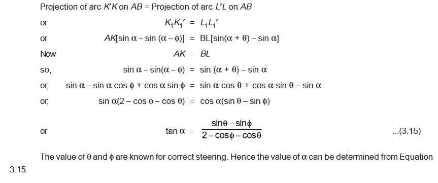
Determination of angle α
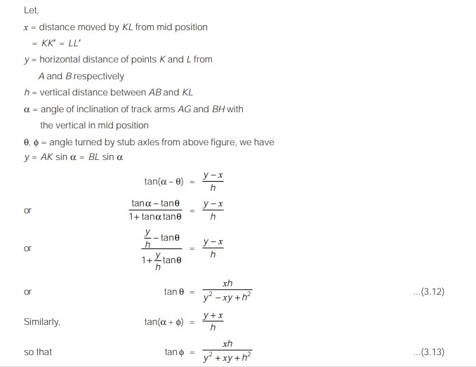

or
Generally, b/l = 0.4 to 0.5, so that of α = 11.3° to 14.1°. There will be friction and more wear due to sliding
pairs in the Davis steering gear. It fulfills the fundamental equation of gearing in all the positions. However, due to
easy wearing it becomes inaccurate after some time.
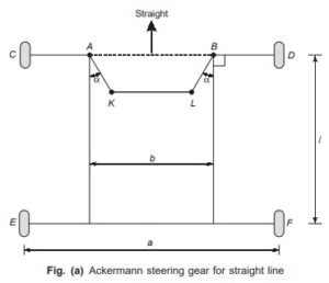
Ackermann Steering Mechanism
The Ackermann steering gear has only turning pairs. Fig. (a) shows the steering gear for straight drive. The turning pairs are : AK, KL, LB and AB. The two short arms AK and BL are of equal length and are connected by pin-joints with front wheel axle AB at A and B respectively. AC and BD are the stub axles so that CAK and DBL form bell-crank levers. ABLK form a four-bar linkage. KL is the track rod.
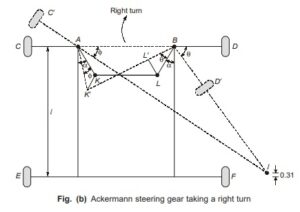
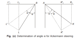
Determination of angle α
Consider the Ackermann steering gear, as shown in figure (b) taking a right turn. The instantaneous centre I
lies on a line parallel to the rear axis at a distance of approximately 0.3 l above the rear axis. It may be seen that the
whole mechanism of the Ackermann steering gear is on the back of the front wheels. From figure (c), we have,
<< Previous | Next >>
Must Read: What is the Theory of Machines?
Dear Aspirants,
Your preparation for GATE, ESE, PSUs, and AE/JE is now smarter than ever — thanks to the MADE EASY YouTube channel.
This is not just a channel, but a complete strategy for success, where you get toppers strategies, PYQ–GTQ discussions, current affairs updates, and important job-related information, all delivered by the country’s best teachers and industry experts.
If you also want to stay one step ahead in the race to success, subscribe to MADE EASY on YouTube and stay connected with us on social media.
MADE EASY — where preparation happens with confidence.
MADE EASY is a well-organized institute, complete in all aspects, and provides quality guidance for both written and personality tests. MADE EASY has produced top-ranked students in ESE, GATE, and various public sector exams. The publishing team regularly writes exam-related blogs based on conversations with the faculty, helping students prepare effectively for their exams.
