Data Transmission Schemes
As we have studied earlier about the base band pulse transmission, we have seen that the output of a PCM code system is a string of 1’s and 0’s. If they are to be transmitted over copper wires, they can be directly transmitted as appropriate voltage levels using line code. But if they are transmitted through space using antenna, some form of modulation has to be used.
In any event, the modulation process makes the data transmission schemes possible involves switching (keying) the amplitude, frequency or phase of sinusoidal carrier in some fashion in accordance with incoming data. Thus, there are three basic signalling schemes and they are known as amplitude shift keying (ASK), frequency shift keying (FSK) and phase shift keying (PSK) and this is called bandpass transmission of signals.
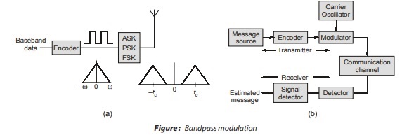
Process of bandpass transmission can be explained from Figure- (b) as follows. Message source emits symbols m1, m2, ⋅ ⋅ ⋅ mm and let their probability of transmission is p1, p2, ⋅ ⋅ ⋅ pm. If not specified then we can assume that all symbols are equiprobable in transmission. Then probability of transmission of any symbol is
p(mi) = 1/m for i = 1, 2,…,m.
Then modulator takes the message source output mi and codes it into distinct signals si(t) suitable for transmission
over the channel. The duration of si(t) is same as that of symbol mi i.e. T seconds. As si(t) is of a finite duration, so its energy can be given as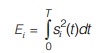
Let communication channel has two characteristics:
- It is linear and its bandwidth is wide enough to accommodate transmission of signal si (t) with negligible or no distortion.
- Channel noise w(t) is sample function of a zero mean white Gaussian noise process. Hence, received signal can be expressed as
![]()
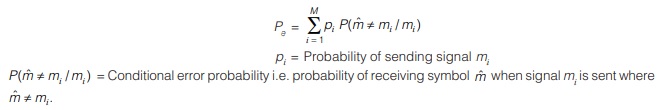
The main task of receiver is to observe the signal si(t) for ‘T’ duration and estimate the message symbol mi from it. But this estimation is complex in the way that value of si(t) may change due to presence of channel noise and receiver will make occasional errors. So, the receiver is to be designed to minimize probability of error, defined as
Digital Modulation Schemes
Basically, there are two types of digital modulation schemes:
Binary schemes: In Binary schemes: this, we send one of the two possible signals during each signalling interval of duration Tb. Examples are: ASK, FSK and PSK.
M-ary schemes: In this, we M-ary schemes: send one of the M-possible signals during each signalling interval of duration T. Number of possible signals, M = 2n and the signalling interval T = nTb. Each of the M signals is called a symbol, which consists of n = log2M bits.
Example are: M-ary PSK, MSK, QAM, QPSK etc. These techniques are discussed one by one in following sections.
Quadrature Amplitude Modulation
In PSK technique, one symbol is distinguished from other in phase, but all the symbols are same in amplitude in M-ary PSK. As we know that, the ability of receiver to distinguish between one signal vector from another depends on distance between vector end points. Hence noise immunity will improve if signals differs not only in phase but also in amplitude. Such a system is called as amplitude and phase shift keying system. It is also known as quadrature amplitude modulation. QAM is a form of digital modulation similar to PSK except the digital information is in both amplitude and phase of transmitted carrier.
Signal Space Representation of QAM
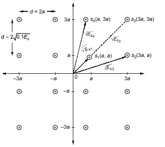
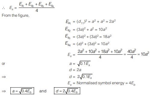
We want to transmit a symbol consisting of 4-bits. This means that N = 4 and there are 24 = 16 possible symbols. Hence the QASK system, we should be able to generate 16 different distinguishable signals. A possible geometric representation of 16 symbols is shown in figure. Each signal point is equally distant from its nearest neighbours.
Differential Phase Shift Keying (DPSK)
- DPSK is called non-coherent version of PSK. It doesn’t need any synchronous carrier at demodulator.
- Input sequence of binary bits is modified such that next bit depends on previous bit.
- On the receiver side, the previous received bits are used to detect the present bit.
DPSK Transmitter
It consists of two operations:
(a) Differential encoding of input binary sequence. (b) PSK of encoded sequence.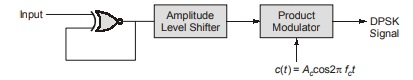
• The digital information content of binary content is encoded in terms of signal transitions.
• Let us consider a message signal with m(t) = 1010 and reference bit = 1 and find DPSK signal of it.
• m(t) = 1 0 1 0 (Reference bit = 1)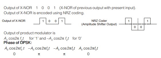
DPSK Receiver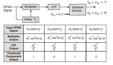
Advantages of DPSK
- No need of synchronization or no need of carrier at receiver end.
- Bandwidth requirement is less.
- One input bit transmission depends on previous bit as well as present bit.
Hence, T = 2Tb (T = Symbol duration ; Tb = Bit duration)
BW = 2/T = 1/Tb = fb
Hence, minimum bandwidth in DPSK is equal to fb = maximum baseband signal frequency.
Drawbacks
- Probability of error is higher.
- As DPSK uses two successive bits for its reception, error in first bit creates error in second bit. Hence error propagation is more.
- Noise interference is more.
Minimum Shift Keying(MSK)
In digital radio communication, one of the key concern is the power in the sidelobes. A spectrum rich in harmonic content is likely to cause interference with the nearby channels. The abrupt change in phase in PSK gives rise to spectral components in high frequencies. Minimum shift keying (MSK) address this by changing phase in a continuous manner and is also known as continuous phase FSK (CPFSK).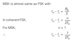
Two important differences between QPSK and MSK
In MSK the baseband waveform, that multiplies the quadrature carrier, is much “smoother” than the abrupt rectangular waveform of QPSK. While the spectrum of MSK has a main center lobe which is 1.5 times as wide as the main lobe of QPSK, the side lobes in MSK are relatively much smaller in comparison to the main lobe, making filtering much easier.
The waveform of MSK exhibits phase continuity, i.e. there are not abrupt phase changes as in QPSK. As a result we avoid the Inter Symbol Interference(ISI) caused by nonlinear amplifiers.
Note: Most important and useful feature of MSK is its phase continuity.
Bandwidth of MSK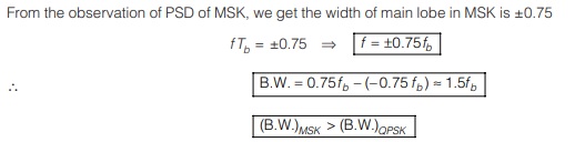
Advantages of MSK
- The MSK waveforms are smoother as compared to QPSK.
- MSK have continuous phase in all the cases whereas QPSK has abrupt phase shift of π/2 or π.
- MSK does not have amplitude variations whereas QPSK have abrupt amplitude variation.
- Main lobe of MSK is wider than QPSK so MSK contains around 99% of signal energy.
- To avoid ISI, QPSK needs BPF but in MSK it is not required.
Disadvantages of MSK
- The generation and detection of MSK is slightly complex, because of incorrect synchronization, phase jitter can be present in MSK.
<< Previous | Next >>
Must Read: What is Communication?
Dear Aspirants,
Your preparation for GATE, ESE, PSUs, and AE/JE is now smarter than ever — thanks to the MADE EASY YouTube channel.
This is not just a channel, but a complete strategy for success, where you get toppers strategies, PYQ–GTQ discussions, current affairs updates, and important job-related information, all delivered by the country’s best teachers and industry experts.
If you also want to stay one step ahead in the race to success, subscribe to MADE EASY on YouTube and stay connected with us on social media.
MADE EASY — where preparation happens with confidence.
MADE EASY is a well-organized institute, complete in all aspects, and provides quality guidance for both written and personality tests. MADE EASY has produced top-ranked students in ESE, GATE, and various public sector exams. The publishing team regularly writes exam-related blogs based on conversations with the faculty, helping students prepare effectively for their exams.
