Optimum Receivers for AWGN Channels
In analog communication, the user objective is to achieve high fidelity in waveform reproduction. Hence, the suitable performance criterion is the output signal to noise ratio. The choice of criteria indicates that signal to noise ratio reflects the quality of message and is related to the ability of listener to interpret a message. In digital communication system, the transmitter input is chosen from a finite set of possible symbols. The objective at the receiver is not to reproduce the waveform that carries the symbol with fidelity, instead the receiver aims to accurately determine which particular symbol was transmitted among the possible symbols. Because the symbol is represented by a particular waveform at the transmitter, our main goal is to decide from noisy signal, which particular waveform was originally transmitted. The appropriate figure of merit in digital communication system is probability of error (also known as bit error rate).
In this chapter, we will consider only the effect of white noise on performance of different communication systems.
White noise is the noise whose power spectral density is uniform over entire frequency range of interest. The white noise is called so because it contains all the frequency components in equal proportion. This is analogous with white light which is superposition of all visible spectral components. It is also called as Gaussian noise because it has a Gaussian distribution i.e. the PDF of white noise has shape of Gaussian PDF.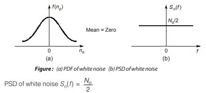
The above equation shows that power spectral density is independent of frequency. As No is constant, PSD is uniform over entire frequency range including positive and negative frequencies.
No = kTe (K = Boltzmann constant, Te = Equivalent noise temperature of system)
Detection of Signal in Noise
As we have studied earlier the coherent detectors for digital carrier modulation (ASK, FSK, PSK etc.), now our main aim is to detect these signals in noise. 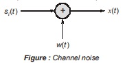
When the signal is transmitted through channel, then due to presence of channel noise, it is likely that received signal will be different from the transmitted message signal.
Now, the main objective of the receiver is to estimate the message symbol mi (or (si(t)) from the received signal x(t). When the receiver signal x(t) is applied to bank of correlators, correlator outputs define vector x.
Hence, at the receiver side, we are given observation vector x and the requirement is to generate/estimate message signal mi . Like the message point has been represented in Euclidean space, similarly, the observation vector x can be represented by a point in the same space. x can lie anywhere in a space centred about si depending on the presence of noise. It wanders about the message point in random fashion.
Let Z = N-dimensional space of all possible observation vectors x. This is refer to as observation space. Z is partitioned into M-decision regions (z1, z2 ⋅ ⋅ ⋅ zm). Partitioning of observation space into decision regions for
case when N = 2 and M = 4 if all symbols are transmitted equally likely is as shown in figure.
But representation of received signal x (t) is not that easy because of the presence of the noise w(t). When x (t) is applied to bank of correlator, output will be observation vector x. Thus x differs from si by the difference of noise vector, w.
Probability of Error
If message signal mi (or equivalently, signal vector si) is transmitted, and an observation vector x is received, then an error occurs if received signal point represented by x doesn’t fall inside region zi associated with message point represented by si.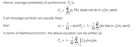
Matched Filter
Definition : If a filter generates an output to maximize the output peak power ratio to mean noise power within its frequency response then it is called a matched filter.
Matched filter is called so because it matches its impulse response according to the incoming signals. The best example of the matched filter is pulse compression because the impulse response can be matched with input pulse signals.
The signal to noise ratio maximization is possible even for non-Gaussian noise.
Consider a receiver model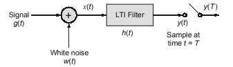
h(t) = Impulse response of LTI filter
x(t) = g(t) + ω(t)
T = Arbitrary observation interval
g(t) = Binary symbol 1 or 0
w(t) = Sample function of white noise process of zero mean and power spectral density No/2
Function of receiver is to detect the pulse signal g(t) from received signal x(t). The design of the filter is to be optimized to minimize the effects of noise.
As the filter is linear
y(t) = go(t) + n(t)
where go(t) and n(t) are produced signal and noise components of input x(t) respectively.
For proper noise free detection, signal component go(t) >> noise component n(t). This can be done by making the instantaneous power in output signal go (t) measured at time t = T as large as possible compared with average power of output noise n(t) i.e. peak pulse signal to noise ratio should be maximized
SNR = | go(T) |2/ E[n2-(t)]
<< Previous | Next >>
Must Read: What is Communication?
Dear Aspirants,
Your preparation for GATE, ESE, PSUs, and AE/JE is now smarter than ever — thanks to the MADE EASY YouTube channel.
This is not just a channel, but a complete strategy for success, where you get toppers strategies, PYQ–GTQ discussions, current affairs updates, and important job-related information, all delivered by the country’s best teachers and industry experts.
If you also want to stay one step ahead in the race to success, subscribe to MADE EASY on YouTube and stay connected with us on social media.
MADE EASY — where preparation happens with confidence.
MADE EASY is a well-organized institute, complete in all aspects, and provides quality guidance for both written and personality tests. MADE EASY has produced top-ranked students in ESE, GATE, and various public sector exams. The publishing team regularly writes exam-related blogs based on conversations with the faculty, helping students prepare effectively for their exams.
