The Slider Crank Chain
When one of the turning pairs of a four-bar chain is replaced by a sliding pair, it becomes a single slider- crank chain or simply a slider-crank chain.
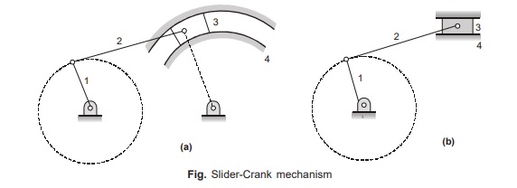
In fact, the slider-crank mechanism, which has a well-known application in engines, is a special case of the crank-rocker mechanism. Notice that if rocker 3 in Fig. (a) is very long, it can be replaced by a block sliding in a curved slot or guide as shown. If the length of the rocker is infinite, the guide and block are no longer curved.
Rather they are apparently straight, as shown in Fig. (b), and the linkage takes the form of the ordinary slider-crank mechanism.
Planar Mechanism with Lower Pairs
Taking a different link as the fixed link, the slider-crank mechanism shown in Fig. (a) can be inverted into the
mechanism shown in Fig. (b), (c) and (d)
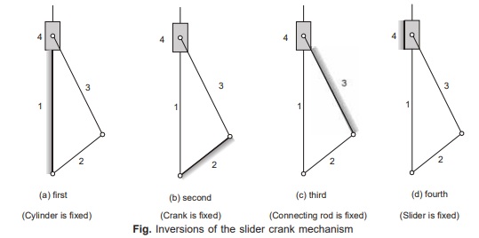
First Inversion Fig. (a)
This inversion is obtained when link 1 (i.e; cylinder) is fixed.
Applications
• Reciprocating engine
• Reciprocating compressor
Second Inversion Fig. (b)
Fixing of the link 2 (i.e; crank) of a slider-crank chain results in the second inversion.
Applications
• Whitworth quick return mechanism
• Rotary engine (GNOME engine)
Third Inversion Fig. (c))
By fixing the link 3 (i.e; connecting rod) of the slider-crank mechanism, the third inversion is obtained.
Applications
• Oscillating cylinder engine
• Crank and slotted-lever mechanism
Fourth Inversion Fig. (d))
If the link 4 (i.e., slider) of the slider-crank mechanism is fixed, the fourth inversion is obtained.
Applications
• Hand pump
| Summary of Slider Crank Chain and its Inversions | ||||
|---|---|---|---|---|
| Mechanism | Links | |||
| Fixed | Rotates | Oscillates | Reciprocates | |
|
Single slider crank chain |
1 | 2 | 3 | 4 |
|
INVERSIONS : |
||||
|
Pendulum pump |
4 | 2 | 3 | 1 |
|
Oscillating cylinder engine |
3 | 2 | 4 |
1 |
| Crank-slotted lever | 3 | 2 | 4 |
1 |
| Whitworth mechanism | 2 | 3 | 1 |
4 |
| Gnome engine | 2 | 3 | 1 |
4 |
Double Slider Crank Chain
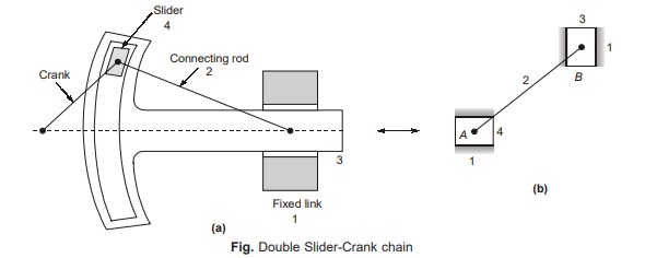
A kinematic chain consisting of two turning pairs and two sliding pairs is called double slider-crank chain as shown in Fig. Links 3 and 4 reciprocate, link 2 rotates and link 1 is fixed. Two pairs of the same kind are adjacent.
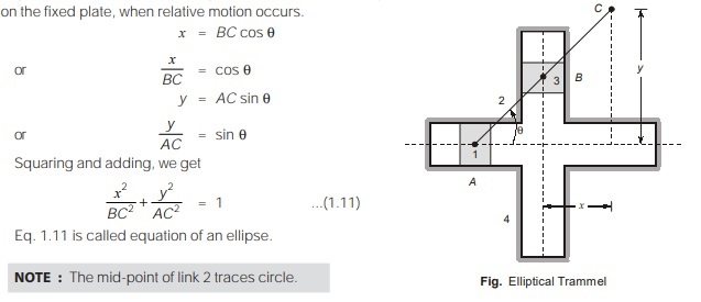
First Inversion (Elliptical Trammel)
It is a device to draw an ellipse. Fig. shows an elliptical trammel in which two grooves are cut at right angles in a plate that is fixed. The plate forms the fixed link 4. Two sliding blocks are fitted into the grooves.
The slides form two sliding links 1 and 3. The link joining slides form the link 2. Any point on link 2 or on its extension traces out an ellipse on the fixed plate, when relative motion occurs.
Second Inversion (Scotch Yoke)
If any of the slide-blocks of the first inversion is fixed, the second inversion of the double-slider-crank chain is obtained as shown in Figure (a). This mechanism gives SHM. Its early application was on steam pumps, but it is now used as a mechanism on a test machine to produce vibrations. It is also used as a sine-cosine generator for computing elements Figure [(a) and (b)] shows a sketch of scotch yoke mechanism.
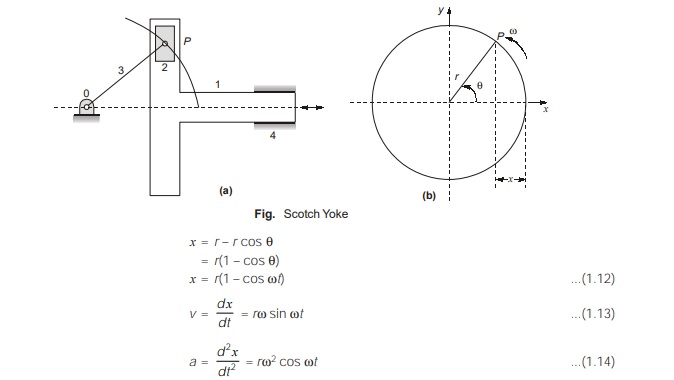
A Scotch-Yoke mechanism is used to convert the rotary motion into a sliding motion. As the crank 3 rotates, the horizontal portion of the link 1 slides or reciprocates in the fixed link 4
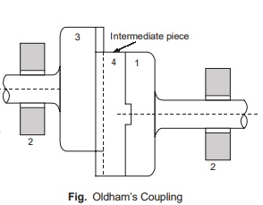
Third Inversion (Oldham’s coupling)
The Oldham’s coupling shown in figure is used to connect two parallel shafts, the distance between whose axes is small and variable. The shafts connected by the coupling rotates at the same speed. The shafts have flanges at the ends, in which slots are cut. These form links 1 and 3. An intermediate piece circular in shape and having tongues at right angles on opposite sides, is fitted between the flanges of the two shafts in such a way that the tongues of the intermediate piece get fitted in the slots of the flanges. The intermediate piece forms link 4, which slides or reciprocates in links 1 and 3. The link 2 is fixed
Maximum sliding speed of each tongue along at slot
= Distance between the axes of the shafts × angular velocity of each shaft………………………….. (1.15)
<< Previous | Next >>
Must Read: What is the Theory of Machines?
Dear Aspirants,
Your preparation for GATE, ESE, PSUs, and AE/JE is now smarter than ever — thanks to the MADE EASY YouTube channel.
This is not just a channel, but a complete strategy for success, where you get toppers strategies, PYQ–GTQ discussions, current affairs updates, and important job-related information, all delivered by the country’s best teachers and industry experts.
If you also want to stay one step ahead in the race to success, subscribe to MADE EASY on YouTube and stay connected with us on social media.
MADE EASY — where preparation happens with confidence.
MADE EASY is a well-organized institute, complete in all aspects, and provides quality guidance for both written and personality tests. MADE EASY has produced top-ranked students in ESE, GATE, and various public sector exams. The publishing team regularly writes exam-related blogs based on conversations with the faculty, helping students prepare effectively for their exams.
