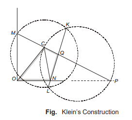
Kleins construction
For a slider-crank mechanism, a simpler method to construct constant velocity and acceleration polygon on the configuration diagram itself has been suggested by Klein. According to him, the line representing crank in the configuration diagram also represents velocity and acceleration of the moving end in the velocity and acceleration diagrams respectively.
Consider a configuration diagram of a slider-crank mechanism as shown in Fig. Let r be the length of crank OC.
Velocity Polygon : Let r represents velocity Vco. Extend the line PC to intersect line drawn perpendicular to OP through O at point M. The triangle OCM represents velocity polygon.
In Fig.: 
- OC represents magnitude of velocity of point C relative to point O. (Vco)
- CM represents magnitude of velocity of point C relative to point P. (Vcp)
- OM represents magnitude of slider velocity (Vpo)
Acceleration Polygon : For acceleration polygon, let r represents acceleration of point C with respect to point O, aco (= ω2r). This assumption gives the scale for acceleration polygon. For construction of acceleration polygon, the following procedure may be used:
- Draw a circle of radius CM with point C as centre of the circle.
- Draw another circle with link CP as diameter and midpoint of the line CP as the centre of the circle.
- Join the points of intersection of these two circles by a straight line KL, which is chord common to both circle. Let this common chord cuts the links CP and OP at point Q and N respectively.
Here, the quadrilateral OCQN is the required acceleration polygon,
- ON → Linear acceleration of slider P
- OC → Centripetal acceleration of crank OC
- CQ → Centripetal acceleration of link CP
- QN → Tangential acceleration of link CP
- CN → Total acceleration of link CP
<< Previous | Next >>
Must Read: What is the Theory of Machines?

