Classification of Gear
Parallel Shafts
- Spur Gears: They have straight teeth parallel to the axes and thus are not subjected to axial thrust due to tooth load.
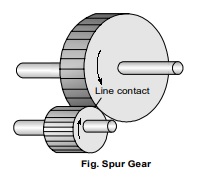
- At the time of engagement of the two gears, the contact extends across the entire width on a line parallel to the axes of rotation.
This results in sudden application of the load, high impact stresses and excessive noise at high speeds.
- Spur Rack and Pinion: Spur rack is a special case of spur gear where it is made of infinite diameter so that the pitch surface is plane. The spur rack and pinion combination converts rotary motion into translatory motion or vice- versa. It is used in lathe in which the rack transmits motion to the saddle.
- Helical gears or Helical spur gears: In helical gears, the teeth are curved. Two mating gears have the same helix angle; but have teeth of opposite hands.
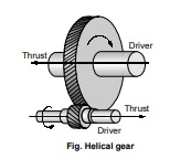
- At the beginning of engagement, contact occurs only at the point of leading edge of the curved teeth. Thus the load application is gradual which result in low impact stresses.
- The helical gears can be used at higher velocities than the spur gears and have greater load – carrying capacity.
- Helical gears have the disadvantage of having end thrust end thrust as t end thrust here is a force component along the gear axis.
- Double-helical and Herring bone Gears: A double – helical gear is equivalent to a pair of helical gears secured together, one having a right hand helix and other a left hand helix.
- No axial thrust is present.
- If the left and the right inclinations of a double – helical gear meet at a common apex at a common apex and there is no groove in between the gear is known as herringbone gear.
- Intersecting Shafts: The motion between two intersecting shafts is equivalent to the rolling of two cones assuming no slipping.
– Straight bevel Gears: The teeth are straight, radial to the point of intersection of the shaft axes and vary in cross- section throughout their length. - Gears of the same size and connecting two shafts at right angle to each other
are known as mitre gears.
– Spiral bevel Gears: When the teeth of a bevel gear are inclined at an angle to the face of the bevel, they are known as spiral bevel or helical bevels.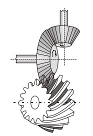
- There is gradual load application and low impact stresses.
- These are used for the drive to the differential of an automobile.
– Zero bevel Gears: Spiral bevel gears with curved teeth but with a zero degree spiral angle are known as zero bevel gears. - Skew Shafts
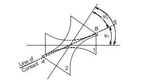
In case of skew (non-parallel, non-intersecting) shafts, a uniform rotary motion is not possible by pure rolling contact. - If the two hyperboloids rotate on their respective axes, the motion between them would be a combination of rolling and sliding action.
- Angle between two shafts will be equal to the sum of the angles of generation of two hyperboloids.
θ = ψ1 + ψ2
- Crossed helical gears: The use of crossed – helical gears or spiral gears is limited to light loads. These gears are used to drive feed mechanism on machine tools, camshafts and oil pumps in I.C. engine.
- Worm Gears: It is a special case of a spiral gear in which the larger wheel usually has a hollow or concave shape.
Classification of Gear according to Peripheral Velocity of Gears
Low velocity gear : 0 – 3 m/s
Medium velocity gear : 3 – 5 m/s
Large velocity gear : >15 m/s
Gear Terminology
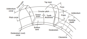
- Pitch Circle: It is an imaginary circle drawn in such a way that a pure rolling motion on this circle gives the motion which is exactly similar to the gear motion.
- Pitch Point: It is a point where the two pitch circles of the mating gears touch each other.
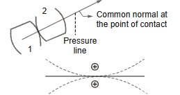
- Pressure angle (Φ): It is the angle between common normal to two gear teeth at the point of contact and the common tangent at the pitch point.
- The standard pressure angles are 14½ °, 20°, 25°.
- Module (m ): It is defined as the ratio of pitch circle diameter (in mm) to the number of teeth.
m = D/T
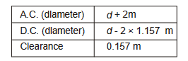
- Addendum Circle : A circle drawn from top of tooth and is concentric to pitch circle.
Addendum is radial distance between pitch circle to the top of tooth. - Dedendum Circle : A circle drawn from bottom of the teeth and concentric with pitch circle.
Dedendum is radial distance between pitch circle and dedendum circle.
Standard proportions for 20° full depth system.
- Circular Pitch (C ) : It is a distance along a pitch circle from one point on a tooth to the corresponding point on the next tooth.
C=πD/T
where, D = Pitch circle-diameter; T = Number of teeth; C = Space width + Tooth thickness
- Diametral Pitch : It is the ratio of number of teeth to the pitch circle diameter but diameter should be in mm.
Pd=T/D
- Relation between circular pitch (C ) and diametral pitch (Pd )
Circular pitch × Diametral pitch = π
- Tooth Thickness: It is the thickness of tooth measured along pitch circle.
- Tooth Space: The space between the consecutive teeth measured along the pitch circle.
- Backlash: It is difference between tooth space and tooth thickness, which is generally provided to avoid jamming due to thermal expansion.
- Face: The portion of tooth profile above the pitch surface.
- Flank :The portion of tooth profile below the pitch surface.
- Profile: The curvature contained by face and flank.
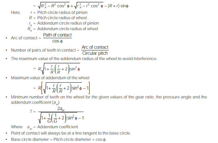
- Path of contact (POC): It is the path travelled by point of contact from the starting of engagement to the end of engagement.
POC = Path of approach + Path of Recess
- Arc of Contact (AOC): It is the path traced by a point on the pitch circle during starting of engagement to the end of engagement.
Law of Gearing
- The law of gearings states the condition which must be fulfilled by the gear tooth profiles to maintain a constant angular velocity ratio between two gears.
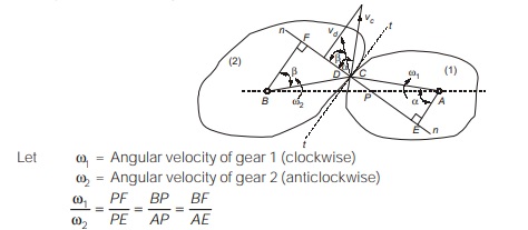
- For constant angular velocity ratio of the two gears, the common normal at the point of contact of the two mating teeth must pass through the pitch point.
- Velocity of sliding
If the curved surfaces of the two teeth of the gears are to remain in contact one can have a sliding motion relative to the other along the common tangent.
= Sum of angular velocities × distance between the pitch point and point of contact.
![]()
Type of Profile
Involute Profile
-
-
- Involute is a curve generated by point on a tangent which rolls on a circle without slipping. The involute profile on a gear will be generated through a generating circle and this generating circle will be known as base circle. It is a fundamental property of a gear its radius will not change in any condition for a gear.
-
- A normal on any point of involute profile will be tangent to the base circle.
- Tooth profile is always generated from base circle and the profile between root circle and base circle will not be of involute type.
- If the centre distance between the two pitch circles varies, the point P is shifted and the speed of the driven gear would vary.
- For a pair of involute gears, velocity ratio is inversely proportional to the pitch circle diameters as well as base circle diameters.
- Path of Contact
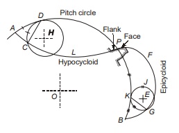
Cycloidal Profile Teeth :
A cycloid is the locus of a point on the circumference of a circle that rolls without slipping on the circumference of another circle. In this type, the faces of the teeth are epicycloids and flanks the hypocycloids.
| Type of tooth | Pressure angle (Φ) | Addendum | Dedendum |
|---|---|---|---|
|
Full depth |
20°
22.5° |
1 m
1 m |
1.157 m
1.35 m |
|
25° |
1 m |
1.25 m |
|
| Stub | 20° | 0.8 m |
1 m |
<< Previous | Next >>
Must Read: What is the Theory of Machines?
Dear Aspirants,
Your preparation for GATE, ESE, PSUs, and AE/JE is now smarter than ever — thanks to the MADE EASY YouTube channel.
This is not just a channel, but a complete strategy for success, where you get toppers strategies, PYQ–GTQ discussions, current affairs updates, and important job-related information, all delivered by the country’s best teachers and industry experts.
If you also want to stay one step ahead in the race to success, subscribe to MADE EASY on YouTube and stay connected with us on social media.
MADE EASY — where preparation happens with confidence.
MADE EASY is a well-organized institute, complete in all aspects, and provides quality guidance for both written and personality tests. MADE EASY has produced top-ranked students in ESE, GATE, and various public sector exams. The publishing team regularly writes exam-related blogs based on conversations with the faculty, helping students prepare effectively for their exams.
