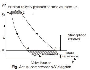
Actual P-V Diagram for Single-Stage Compressor
Theoretical p-V diagram – (1-2-3-4)
Theoretical inlet valve should open at point ‘4’ but in practice it is not opening at point ‘4’, due to the following two main reasons:
- Pressure difference is required across the inlet valve in order to move it.
- Inlet valve inertia
- So negative pressure difference is required to open the valve and called as intake depression.
- Similar situation occurs at 2, at the beginning of delivery stroke. Compressed air is delivered into receiver and hence external delivery pressure is also known as receiver pressure.
- Gas inertia and turbulence also affecting the inlet and delivery.
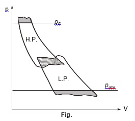
Actual p-V Diagram of for Two Stage Compressor
- Inertia and friction effects, which results in valve flattering and increase the area of diagram slightly and hence their effects is to increase the total work of compression.
- LP and HP diagram overlap due to pressure drop in intercooler.
- Wavy lines during induction and delivery strokes are due to “Flatter” of valve’s disc.
Reciprocating Compressors
- Greater vibration problem.
- Mechanical efficiency is lower compare to rotary compressor because of several sliding and bearing members.
- Pressure ratio per state is 5 to 8.
- Delivery volume is small (250 – 300 m3/min) compared to rotary compressor (2000 – 3000 m3/min).
- Compression efficiency is high at compression ratio above 2.
- Reciprocating air compressors are having isothermal compression where as Rotary air compressors are having isentropic compression.
<< Previous | Next >>
Must Read: What is Power Plant Engineering?
Dear Aspirants,
Your preparation for GATE, ESE, PSUs, and AE/JE is now smarter than ever — thanks to the MADE EASY YouTube channel.
This is not just a channel, but a complete strategy for success, where you get toppers strategies, PYQ–GTQ discussions, current affairs updates, and important job-related information, all delivered by the country’s best teachers and industry experts.
If you also want to stay one step ahead in the race to success, subscribe to MADE EASY on YouTube and stay connected with us on social media.
MADE EASY — where preparation happens with confidence.
MADE EASY is a well-organized institute, complete in all aspects, and provides quality guidance for both written and personality tests. MADE EASY has produced top-ranked students in ESE, GATE, and various public sector exams. The publishing team regularly writes exam-related blogs based on conversations with the faculty, helping students prepare effectively for their exams.
