MESH ANALYSIS
Mesh analysis provides another general procedure for analyzing circuits, using mesh currents as the circuit variables. Recall that a loop is a closed path with no node passed more than once. A mesh is a loop that does not contain any other loop within it.
Nodal analysis applies KCL to find unknown voltages in a given circuit, while mesh analysis applies KVL to find unknown currents. Mesh analysis is not quite as general as nodal analysis because it is only applicable to a circuit that is planar. A planar circuit is one that can be drawn in a plane with no branches crossing one another, otherwise it is non-planar.
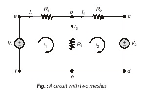
In above figure, for example, paths abefa and bcdeb are meshes, but path abcdefa is not a mesh. The current through a mesh is known as mesh current. In mesh analysis, we are interested in applying KVL to find the mesh currents in a given circuit.
Note:
Although path abcdefa is a loop and not a mesh, KVL still holds. This is the reason for loosely using the terms loop analysis and mesh analysis to mean the same thing.
Steps to Determine Mesh Currents
- Step-1 : Determine if the circuit is a planar circuit. If not, perform nodal analysis instead.
- Step-2 : Count the number of meshes (M). Redraw the circuit if necessary.
- Step-3 : Label each of the M mesh currents. Generally, defining all mesh currents to flow clockwise results in a simpler analysis.
- Step-4 : Write a KVL equation around each mesh. Begin with a convenient node and proceed in the direction of the mesh current. Pay close attention to “–” signs. If a current source lies on the periphery of a mesh, no KVL equation is needed and the mesh current is determined by inspection.
- Step-5 : Express any additional unknowns such as voltages or currents other than mesh current in terms of appropriate mesh currents. This situation can occur if current sources or dependent sources appear in our circuit.
- Step-6 : Organize the equations. Group terms according to mesh currents.
- Step-7 : Solve the system of equations for the mesh currents (there will be M of them).
To illustrate the steps, consider the circuit in Figure above. The first step requires to determine that the circuit is planar or not, observing the circuit we can determine that circuit is planar. Moving to the next step mesh current i1 and i2 are assigned to meshes 1 and 2. Although a mesh current may be assigned to each mesh in an arbitrary direction, it is conventional to assume that each mesh current flows clockwise.
Dear Aspirants,
Your preparation for GATE, ESE, PSUs, and AE/JE is now smarter than ever — thanks to the MADE EASY YouTube channel.
This is not just a channel, but a complete strategy for success, where you get toppers strategies, PYQ–GTQ discussions, current affairs updates, and important job-related information, all delivered by the country’s best teachers and industry experts.
If you also want to stay one step ahead in the race to success, subscribe to MADE EASY on YouTube and stay connected with us on social media.
MADE EASY — where preparation happens with confidence.
MADE EASY is a well-organized institute, complete in all aspects, and provides quality guidance for both written and personality tests. MADE EASY has produced top-ranked students in ESE, GATE, and various public sector exams. The publishing team regularly writes exam-related blogs based on conversations with the faculty, helping students prepare effectively for their exams.
