Basic Nodal
INTRODUCTION
Having understood the fundamental laws of circuit theory (Ohm’s law and Kirchhoff’s law), we are now prepared to apply these laws to develop two powerful techniques for circuit analysis: nodal analysis, which is based on a systematic application of Kirchhoff’s current law (KCL), and mesh analysis, which is based on a systematic application of Kirchhoff’s voltage law (KVL). With these two techniques, we can analyze almost any circuit by obtaining a set of simultaneous equation that are then solved to obtain the required values of current and voltage.
NODAL ANALYSIS
We begin our study of general methods for circuit analysis by considering a powerful method based on KCL, namely nodal analysis.
Nodal analysis provides a general procedure for analyzing circuits using node voltages as the circuit variables. Choosing node voltages instead of element voltages as circuit variables is convenient and reduces the number of equations one must solve simultaneous. In nodal analysis, we are interested in finding the node voltages. Given a circuit with ‘n’ nodes without voltages source, the nodal analysis of the circuit involves taking the following steps.
- Step-1 : Count the number of nodes (N).
- Step-2 : Designate a reference node. The number of terms in your nodal equations can be minimized by selecting the node with the greatest number of branches connected to it.
- Step-3 : Label the nodal voltages (there are N – 1 of them).
- Step-4 : Write a KCL equation for each of the non-reference nodes. Sum the currents flowing into a node from sources on one side of the equation. On the other side, sum the currents flowing out of the node through resistors. Pay close attention to “–” signs.
- Step-5 : Express any additional unknown such as currents or voltages other than nodal voltages in terms of appropriate nodal voltages. This situation can occur if voltage sources or dependent sources appear in our circuit.
- Step-6 : Organize the equations. Group the terms according to nodal voltages.
- Step-7 : Solve the system of equations for the nodal voltages (there will be N – 1 for them).
We shall now explain these steps with the help of an example.
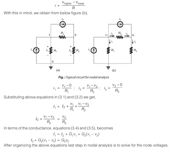
Consider the circuit shown below in the figure (a). The first step is to count the number of nodes in the circuit i.e. three. Now step two in nodal analysis is selecting a node as the reference or datum node. The reference node is commonly called the ground since it is assumed to have zero potential.
Once we have selected a reference node, we assign voltage designation to non-reference nodes. Consider, for example, the circuit in figure (a). Node 0 is the reference node (v = 0), while nodes 1 and 2 are assigned voltages v1 and v2, respectively. Keep in mind that the node voltages are defined with respect to the reference node. As illustrated in below figure (a), each node voltage is the voltage rise from the reference voltage of that node with respect to the reference node. The next step is to apply KCL to each non-reference node in the circuit.
At node 1, applying KCL gives
I1=I2 + i1 + i2
At node 2, I2 + i2=i3
We now apply Ohm’s law to express the unknown currents i1, i2 and i3 in terms of node voltages. The key idea to bear in mind is that, since resistance is a passive element, by the passive sign convention, current must always flow from a higher potential to a lower potential.
Current flows from a higher potential to a lower potential in a resistor.
We can express this principle as
Dear Aspirants,
Your preparation for GATE, ESE, PSUs, and AE/JE is now smarter than ever — thanks to the MADE EASY YouTube channel.
This is not just a channel, but a complete strategy for success, where you get toppers strategies, PYQ–GTQ discussions, current affairs updates, and important job-related information, all delivered by the country’s best teachers and industry experts.
If you also want to stay one step ahead in the race to success, subscribe to MADE EASY on YouTube and stay connected with us on social media.
MADE EASY — where preparation happens with confidence.
MADE EASY is a well-organized institute, complete in all aspects, and provides quality guidance for both written and personality tests. MADE EASY has produced top-ranked students in ESE, GATE, and various public sector exams. The publishing team regularly writes exam-related blogs based on conversations with the faculty, helping students prepare effectively for their exams.
