TWO-PHASE SERVOMOTOR
SERVOMOTOR
For a low-power (~300 W) control application, 2-phase balanced servomotor driven by ac amplifier is used in control applications. The motor torque is controlled by varying the magnitude of ac voltage applied to the control phase (phase a) as shown in fig. (a).
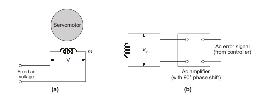
The second phase called the reference phase is excited by a fixed voltage ac source. The control phase voltage is shifted in phase by 90° from the reference phase voltage. The motor torque is reversed by phase reversal of the control phase voltage. For linear stable operation, the torque speed characteristics of the servo motor must be linear with negative slope (torque reducing with increasing speed). The torque speed characteristics of a normally designed induction motor is highly non-linear and is unstable for normal loads in the region from zero speed to speed at breakdown torque. This indeed is the useful region of operation of a servomotor employed in position control systems.
This is obtained by designing a rotor with high resistance so that the maximum torque occurs at a slip of –0.5. Due to high rotor resistance, servo-motor does not develop single-phasing torque which may disturb the control characteristic of the motor.
The torque-speed characteristic of a servomotor for various per unit values of phase voltage are drawn in fig. (c). Low-inertia construction is achieved by using a drag-cup rotor.
Advantages of ac servomotors over dc servomotors are:
Use of a drift-free ac amplifier in the control circuitry.
1. Use of a drift-free ac amplifier in the control circuitry.
2. Low rotor inertia (hence faster response).
3. Rugged maintenance-free rotor construction.
4. No brushes contacting commutator segments.
5. The rotor can with stand higher temperature as it does involve insulation.
AC Tachometers
Carrier frequency signal whose amplitude is proportional to speed is obtained by means of ac tachometers. An ac tachometer is a 2-phase inductive motor with one phase excited from the carrier frequency, while the phase winding is left open-circuited as shown in the figure.
To achieve low-inertia, drag-cup rotor construction is used. The voltage across phase a is proportional to rotor speed while it has phase shift close to 90°.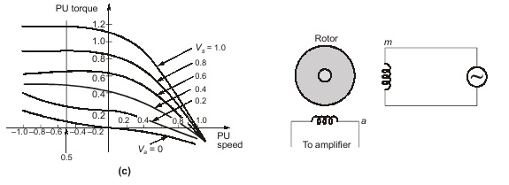
For very small or very large rotor X2/R2 ratio, Va speed relationship is linear. Low X2/R2 gives low speed sensitivity but a wide linear range and vice versa. An intermediate value of X2/R2 meets the general requirements. The phase shift is slightly less than 90° and is quite insensitive to speed. AC tachometers are used in 400-Hz control systems. Pick-up from stray fields is eliminated by soft-iron shields.
Dear Aspirants,
Your preparation for GATE, ESE, PSUs, and AE/JE is now smarter than ever — thanks to the MADE EASY YouTube channel.
This is not just a channel, but a complete strategy for success, where you get toppers strategies, PYQ–GTQ discussions, current affairs updates, and important job-related information, all delivered by the country’s best teachers and industry experts.
If you also want to stay one step ahead in the race to success, subscribe to MADE EASY on YouTube and stay connected with us on social media.
MADE EASY — where preparation happens with confidence.
MADE EASY is a well-organized institute, complete in all aspects, and provides quality guidance for both written and personality tests. MADE EASY has produced top-ranked students in ESE, GATE, and various public sector exams. The publishing team regularly writes exam-related blogs based on conversations with the faculty, helping students prepare effectively for their exams.
