Sulphur Hexa Fluoride Circuit Breakers
What is Hexa Fluoride (SF6)?
Sulphur Hexa Fluoride (SF6) gas has the following properties which makes it superior to other mediums such as oil and air for use in circuit breakers.
- It is a heavy, chemically inert, non-toxic and non-inflammable gas.
- It has a very high dielectric strength (two to three times better than of air).
- Due to the excellent insulating properties of SF6 gas, reduced electrical clearances are required.
- SF6 is stable upto 500°C temperature.
- Its heat transfer property is about 1.6 times of that of air owing to it’s high density.
- Due to the small thermal time constant of SF6, it can be stored at a relatively smaller pressure than that of air.
- Due to it’s electronegatively property, its molecules rapidly absorb free electrons in the arc path forming heavy slow moving negative ions, which are ineffective as current carries. Due to this reason it has a superior arc quenching ability.
- Its arc time constant is in few µs.
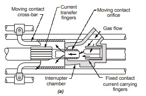
In these type of CBs, the gas blast speeds need not be as high as in ABCB. Here, the gas is hermetically sealed inside the breaker body at a pressure of about 3 atm. Using a “puffer mechanism”, high pressure is obtained which is required for generating the gas blast of sufficient speed. Below figure shows the basic construction of a SF6 circuit breaker.
There are two basic parts of a SF6 circuit breakers which are as follows:
- The interrupter: It consists of two contacts one fixed and another moving. These contacts aresurrounded by interrupting nozzles and a blast shield to control the arc displacement. When the moving contact is withdrawn, an arc is drawn between the nozzles and arcing probe, which is quenched by the gas flow from the high pressure to the low pressure system.
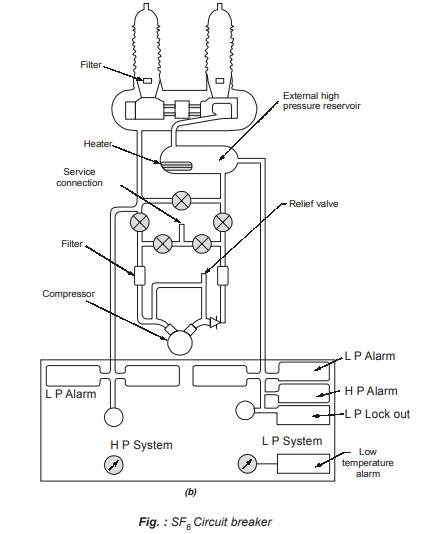
- The gas system: It consists and deals with gas only. It uses a compressor to maintain the required pressure and a heater backed with a thermostat set at 16°C to prevent the liquidification of gas. Here, the closed gas cycle system is used as shown in figure (b) (SF6 circuit breaker).
Advantages of SF6 CBs
- It gives a noiseless operation.
- Current chopping is minimum in SF6 breakers.
- SF6 gas has very high dielectric strength due to which electrical clearances are very much reduced.
- Its performance is independent of ambient conditions.
- Due to small arcing time it has an outstanding arc quenching properties resulting into less erosion of contact.
- Due to low gas velocity and pressure employed in SF6 CBs, current chopping is prevented and capacitive currents are interrupted without restriking.
- No insulation tracking takes place.
- These CBs are non-inflammable and hence no fire-hazard problems.
- It’s heat capacity below 6000°K is much larger than that of air and helps in continuous cooling of the arc zone.
Applications of SF6 Circuit Breakers
SF6 circuit breakers are widely used in a voltage range of 6.6 kV to 765 kV and 20-60 kA rupturing capacity. These CBs are becoming more popular day-by-day.
Different Forms of Stability
For the purpose of analysis there are mainly three stability conditions which are namely
1. Steady state stability
2. Transient stability
3. Dynamic stability
Steady State Stability
- Steady state stability is defined as the ability of an electric power system to maintain synchronism between machines within the system and an external tie line following a small slow disturbance.
- The small slow disturbance may constitute normal load fluctuations, the actions of automatic voltage regulators and turbine governors.
- The “steady state stability limit” refers to the maximum power which can be transferred through the system without loss of stability.
- Whenever the maximum power transfer exceeds the steady state limit of the system, individual machines or groups of machines cease to operate in synchronism and a wide fluctuations of the voltage occurs.
- System non-linearities are generally ignored in steady-state analysis.
- The study time for steady state analysis is usually few seconds to several hours.
Transient Stability
- Transient stability deals with the study of large sudden disturbances occurring in the system.
- Such large sudden disturbances include application of faults, clearing of faults, sudden change in load, and inadvertent tripping of lines and generators.
- “Transient stability limit” refers to the maximum power which can be transferred through the system without the loss of stability under sudden disturbances.
- System non-linearities play a vital role in transient state analysis.
- Transient stability is the ability of the system to remain in synchronism during the period following a disturbance and prior to the time that the governors can act.
- The study time is less than one second for transient stability analysis.
Dynamic Stability
- Dynamic stability is the ability of a power system to remain in synchronism after the “initial swing” (transient stability period) until the system has settled down to the new-steady state equilibrium condition.
- The study time for dynamic stability analysis is usually between 30 minutes to 80 minutes.
- When sufficient time is elapsed after a disturbance, the governors of the prime-movers react to increase or reduce input energy, as may be required, to re-establish a balance between energy input and the existing electrical load.
Type of HVDC Link or Transmission Modes
The DC links can be divided into the following three types :
1. Monopolar Link
- A monopolar link has only one energized conductor normally of negative polarity and uses ground or sea water as the return path. Earth has a much lower resistance to DC as compared to AC. The negative polarity is preferred on overhead lines due to lesser radio interference and corona loss.
Below figure shows a monopolar HVDC link.
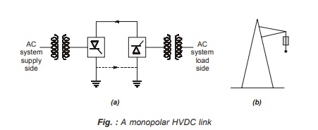
- Here, the return path is provided by permanent earth or sea. Monopolar line/link is more economical than a bipolar link because the ground return saves the cost of the one metallic conductor and losses in it. Monopolar HVDC links were used only for low power rating and mainly for cable transmission. A monopolar link can be converted into a bipolar link by adding an additional substation pole and transmission pole.
- Monopolar HVDC link has only the rating equal to half of corresponding bipolar link rating and hence, not economically competitive with EHV AC schemes for submarine cables, longer than 25 km and of power rating of about 250 MW. For such cable transmission high voltage ac scheme is not technically feasible due to large charging currents with ac cables beyond thermal limit.
Bipolar HVDC Link
This is most widely used dc link for overhead long distance. It has two conductors, one positive and the other negative potential of the same magnitude (e.g., ±500 kV). At each terminal, two converters of equal rated voltages are connected in series on the DC side. The neutral points are grounded, at one or both ends. If both the neutrals are grounded, the two poles operate independently. If the currents in the two conductors are equal, the ground current is zero. If one conductor develops a fault, the other conductor can supply half the rated load.
A bipolar link is shown below in figure.
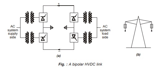
A bipolar transmission has two circuits which are almost independent of each other. A bipolar link can be operated as a monopolar link in an emergency situation. Power rating of one pole is about half of bipole power rating. Thus, the reliability of a bipolar line is equal to that of a double circuit 3-phase line although it has only two conductors instead of 6 for 3-phase line.
Homopolar HVDC Link
- A homopolar link has two or more conductor, all having the same polarity (usually negative), as the corona loss and radio interference get reduced, and it always operates with ground as the return path. If one of the conductors develops a fault, the converter equipment can be reconnected so that the healthy conductor can supply more than 50% of the rated power.
- A homopolar DC link is shown below in figure.
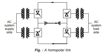
- A homopolar DC link has limited application.
<< Previous | Next >>
Must Read: What is Power Systems?
Dear Aspirants,
Your preparation for GATE, ESE, PSUs, and AE/JE is now smarter than ever — thanks to the MADE EASY YouTube channel.
This is not just a channel, but a complete strategy for success, where you get toppers strategies, PYQ–GTQ discussions, current affairs updates, and important job-related information, all delivered by the country’s best teachers and industry experts.
If you also want to stay one step ahead in the race to success, subscribe to MADE EASY on YouTube and stay connected with us on social media.
MADE EASY — where preparation happens with confidence.
MADE EASY is a well-organized institute, complete in all aspects, and provides quality guidance for both written and personality tests. MADE EASY has produced top-ranked students in ESE, GATE, and various public sector exams. The publishing team regularly writes exam-related blogs based on conversations with the faculty, helping students prepare effectively for their exams.
