
Hydro-electric Power Plants
What is hydraulic electric power?
Hydro-electric power is the power obtained from the energy of falling water whereas hydro-electric power plants is the power plant utilizing the potential energy of water at a high level for the generation of the electrical energy.
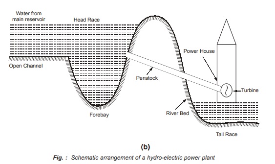
Below given figures shows the schematic arrangement of a hydro-electric plant.
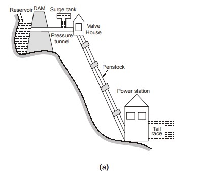
The various elements of hydro-electric power plant are explained as follows:
1. Reservoir: The purpose of reservoir in hydro-electric power station is to store water during rainy season and supply the same during dry season and hence it supplies water to the turbines according to the load on the power plant. There are two types of reservoir namely natural reservoir natural reservoir which is a lake in high mountain and the other is an artificial reservoir artificial reservoir which is made by constructing a dam across the river.
2. Dam: Dam in a hydro-electric plant is used to create an artificial head and to provide the pondage, storage or the facility of diversion into conduits. Dams are made of concrete or stone masonry, earth or rock fill.
3. Forebay: The forebay is used as a “regulating reservoir” storing water temporarily during light load and providing the same for initial increases on account of increasing load during which water in the canal is being accelerated. A forebay is an enlarged body of water just above the intake which is used to store water temporarily to meet the hourly load fluctuations. A forebay is not required if the hydro-electric plant is located just at the base of the dam but, if the plants are situated away from the storage reservoir, a forebay is a must requirement.
4. Spillway: During flood periods, the reservoir becomes full and water overflow. Spillway is used to discharge the overflow water to the down stream side in a situation of flood. A spillway is made up of concrete and is provided with water discharge opening shut off by metal control gates.
5. Intake: Intake is the structures at the intake of conduits, tunnels and flumes and helps in diverting and preventing the entry of debris and ice into the turbines. Screens or trash-racks are fitted directly at the intake to prevent the debris from going into the take.
6. Surge tank: When the load on the generator is reduced, the governor closes the turbine gates and thus create an increased pressure in the penstock. This results into a phenomenon called “Water hammer” which may cause the penstock to burst if it fails to withstand the pressure. This undesirable phenomenon of water hammer is avoided by using a small storage reservoir called “Surge tank”, Surge tank is located as close to the power station as possible. When the load demand is reduced on the power station then, it causes rise in water level in the surge tank which produces a retarding head and reduces the velocity of water in the penstock and hence avoiding the undesirable phenomenon called “Water hammer”.
When the load on the plant is increased, the governor causes the turbine to open the gates in order to allow more water to flow through the penstock to supply the increased load and there is a tendency to cause a vacuum or a negative pressure in the penstock. Under such conditions, the additional water flows out of the surge tank. As a result, water in the surge tank falls, an accelerating head is created and flow of water in the penstock is increased.
Hence, surge tank helps in stabilizing the velocity and pressure in the penstock and reduces water hammer and negative pressure and vacuum. The surge tanks are usually provided at the junction of the pressure tunnel and the penstock.
7. Penstock: Penstock is a closed conduit which connects the forebay or surge tank to the scroll case of the turbine. In case of high head plants, a single penstock is provided. Penstocks are built of steel or reinforced concrete. When the penstock used is very long care must be taken to protect the conduit against water hammer. The thickness of penstock must be such that it can withstand both the normal hydrostatic pressure and also the sudden surges both above and below normal caused by fluctuations in load and by emergency conditions.
8. Valves and Gates: Gates are used in low head plants at the entrance to the turbine casing to shut-off the flow and provide for unwatering the turbine for inspection and repairs. Valves are used at the entrance to the turbine casing if a long or medium length penstocks is used in the hydro-power plant.
9. Trash Racks: Trash racks are used to prevent the ingress of floating and other material to the turbine. These are built up from long, flat bars set vertically or nearly so and spaced in accordance with the minimum width of water passage through the turbine.
10. Tail Race: After the useful work is done by water, it is discharged to the tail race.
11. Draft Tube: It is an air tight pipe of suitable diameter attached to the runner outlet and conducting water down from the wheel and discharging it under the surface of the water in the tail race. With the help of draft tube operating head on the turbine is increased resulting in increase in output and efficiency.
12. Prime-movers or Water turbines: In hydro-electric plants water turbines serve the purpose of prime mover which converts the kinetic energy of water into mechanical energy which is further utilized to drive the alternators for generating electrical energy.
Pumped Storage Power Plants
It is a unique design of peak load plant in which the plant pumps back all or a portion of its water supply during low load period. In this type of power plant, a tail race pond and a head race pond is connected through a penstock. Below figure shows a schematic diagram of a pumped storage power plant.
Construction and Working
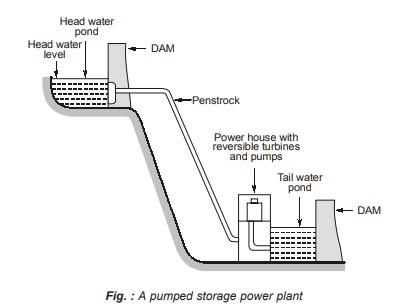
The generating pumping plant is at the lower end. The plant utilizes some of the surplus energy generated by the base load plant to pump the water from the tail race water pond into the head race water pond during off peak hours. During peak hours the turbine drives the generator and the plant generates electrical energy while during off peak hours the generator operates as a motor and drives the turbine which now works as a pump raising the water from the tail water pond to the head water pond.
The turbine used is a francis turbine (or DERIAZ) which is just the reverse of centrifugal pump. The arrangement so used in this type of power plant reduces the capital cost of the plant and improves the operating efficiency and thus results in economic operation. The efficiency of such plant is around 60-70 percent. Pumped storage power plants for peak load supply in interconnected systems are most suitable where the quantity of water available for power generation is insufficient but natural site for construction of high dam exists.
Advantages of Pumped Storage Power Plants
Following are few important advantages of a pumped storage power plant :
- They can be used for load frequency control.
- When the load demand in the system is suddenly increased then, they can be immediately switched on to meet the extra demand.
- Compared to steam and nuclear power plants, peak load can be supplied at a reduced cost when a pumped storage power plant is used.
- The thermal and nuclear power plant can be operated almost at a unity load factor which ensures their economic operation.
- As they can quick start therefore, spinning reserve requirement of the system is reduced.
Disadvantage of a Pumped Storage Power Plant
The only disadvantage of such power plants is that they can not operate as an isolated power plant, i.e., they can be operated only in inter-connected systems where other generating plants such as steam, nuclear and hydro-power plants are available.
Type of Faults in a Power System
There are basically two types of faults occurring in a power system namely:
1. Symmetrical Faults : Those faults on the power system which gives rise to symmetrical fault currents (i.e., equal fault currents in the lines with 120° displacement) is called a symmetrical fault. In other word system remains in balance during pre and post fault condition. e.g.,
(i) Three phase to earth fault (LLLG fault)
(ii) Three phase fault (LLL fault)
2. Unsymmetrical faults : Those faults on the power system which give rise to unsymmetrical fault currents (i.e., unequal fault currents in the lines with unequal phase displacement) are known as unsymmetrical faults. e.g.,
(i) Single line-to-ground faults (L–G)
(ii) Line-to-line fault (L–L)
(iii) Double line-to-ground fault (L–L–G)
Note:
- Line to Ground (LG) fault is the most frequently fault followed by LLG and LLL fault.
- The calculation of symmetrical short-circuit current or symmetrical short-circuit KVA at a certain point in power system is, therefore, very important for the purpose of determination of circuit breaker ratings.
- The different kinds of faults in order of decreasing severity are :
Three phase fault (3-φ fault) > fault) Double line to ground (LLG) fault > Line to line (LLG) (LL) fault > (LL) Single line to ground (LG) fault.
Per Unit System
- In power system, it is usual to express voltage, current, volt-amperes and impedance of an any electrical circuit in per unit or percentage.
- The per unit (pu) value of any quantity is defined as “the ratio of the quantity (in some unit) to it’s base value (in same unit)”.
![]()
Selection of Base Values for pu System
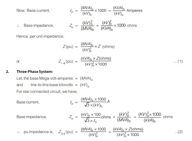
1. Single-Phase System:
Let,
Base Mega volt-amperes = (MVA)b
or, Base kilovolt-ampere = (kVA)b
Base kilovolts = (kV)b
Note:

<< Previous | Next >>
Must Read: What is Power Systems?
Dear Aspirants,
Your preparation for GATE, ESE, PSUs, and AE/JE is now smarter than ever — thanks to the MADE EASY YouTube channel.
This is not just a channel, but a complete strategy for success, where you get toppers strategies, PYQ–GTQ discussions, current affairs updates, and important job-related information, all delivered by the country’s best teachers and industry experts.
If you also want to stay one step ahead in the race to success, subscribe to MADE EASY on YouTube and stay connected with us on social media.
MADE EASY — where preparation happens with confidence.
MADE EASY is a well-organized institute, complete in all aspects, and provides quality guidance for both written and personality tests. MADE EASY has produced top-ranked students in ESE, GATE, and various public sector exams. The publishing team regularly writes exam-related blogs based on conversations with the faculty, helping students prepare effectively for their exams.
