Distribution Systems
What is the distribution system in a power system?
The system (i.e., transmission lines, transformers, etc.) by means of which electrical energy is conveyed from bulk power source or sources (generating stations or major substations supplied over transmission lines) to the consumers is known as “distribution system”. Distribution system is an integral part of any electric power system. Like transmission system, distribution system based on voltage levels can be further classified as
Primary distribution system:
From generating stations, the electrical power is usually transmitted to various substations through extra high tension transmission lines at voltage from 33 kV to 400 kV. At these substations this voltage is stepped down to 11 or 6.6 or 3.3 kV and power at this voltage is conveyed to different substations for distribution and to the bulk supply consumers. Such a system is known as “high voltage” or “primary distribution system”.
Secondary distribution system:
At distribution substations, the voltage is stepped down to 400 volts. From these substations various low voltage (400 volts between phases and 230 volts between phase and neutral) distributors radiate out and feed the consumers. This system of distribution is known as “low voltage” or “secondary distribution system”.
Tertiary distribution system:
A 400 V, 3-phase system is an example of a tertiary distribution system
Distribution system has mainly two components which are as follows:
Feeder: A feeder in a distribution system is a circuit carrying power from a main substation to a secondary substation such that the current loading is the same all along its length. Therefore, the main criterion for the design of a feeder is its current carrying capacity rather than voltage drops.
Distributor: A distributor has a variable loading along its length due to the service conditions, tapping off at intervals by the individual consumers. The permissible voltage variation at consumer terminals must be within ±5%. Excessive voltage variations at consumer terminals lead to equipment failure. Hence, the main criterion for the design of a distributor is the limit on percentage voltage variations.
Remember: Feeders are not tapped in between the sub-transmission substation and the distribution substations, while distributors are tapped throughout at several points to serve the consumers.
Determination of Size of Conductor for Feeders and Distributors
- Practically, ACSR conductors are universally employed for distribution systems (feeders and distributors). However, in case of distributors all aluminium conductors (AAC) can also be used provided the span are same.
- The conductor size for feeder is mainly governed by the current carrying capacity and overall economy. The current carrying capacity is usually determined for a maximum operating temperature of 75°C. After determining the size of the conductor on the basis of current carrying capacity it should be checked that voltage drop in the feeder is not out of the range of the regulating equipment.
- The main consideration for the determination of size of conductor for a distributor is the permissible voltage drop in the line. If the calculated voltage drop is found more than permissible, the conductor size of the distributor is then increased to the next higher standard value and voltage drop calculation is made again. This process is continued till the voltage drop in the distributor is within limits.
Classification of Distribution Systems
- Distribution systems may be classified in various ways.
- According to current, the distribution systems can be classified as
(i) AC distribution
(ii) DC distribution
AC system is universally employed for distribution of electrical power. - According to the construction, the distribution system may be classified as
(i) Overhead distribution system and
(ii) Underground distribution system
Due to low cost, overhead type system is usually employed. Underground distribution system is used where overhead system becomes impractical - According to number of wires, the distribution system is classified as
(i) two-wire; (ii) three-wire; (iii) four-wire distribution systems
In case of dc supply, 3-wire distribution system is usually used due to its advantage over two-wire distribution system. 3-phase, 3-wire system is used for balanced loads such as power loads, 3-phase, 4-wire system is used for unbalanced loads such as light and power loads combined and single phase two-wire system is employed for lighting and small power applications.
• According to the scheme of connections the distribution system may be classified as
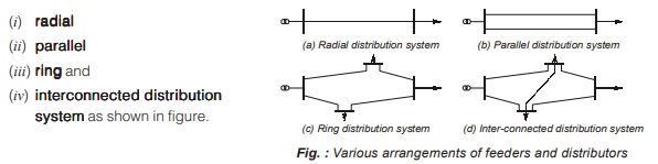
General Construction of a Cable
An underground cable shown in figure consists of following components. 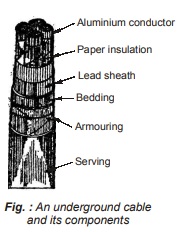
- Cores or conductors
- Insulation or dielectric
- Metallic sheath
- Bedding
- Armouring
- Serving
The above components are explained as follows:
1. Cores or Conductors
A cable may have one or more than one core (conductor) depending upon the type of service for which it is intended. The conductors are made of tinned copper or aluminium and are usually standed in order to provide flexibility to the cable.
2. Insulation or Dielectric
Insulation or dielectric in an underground cable withstands the operating voltage. The aluminium conductor is insulated from each other by paper or varnished cambric or vulcanized bitumen or impregnated paper. For upto 11 kV HV system, paper insulation is used. When oil is used as an insulating material then, it is called oil-filled cables which is used to avoid the formation of voids. Oil -filled cables require small amount of insulation and are used for voltages from 66-400 kV. Sometimes SF6 gas is used as a dielectric medium in a “gas-filled cable”. One advantage of the gas-filled cable is its better heat dissipation by natural convection in the gas. Oil filled and gas filled cables are used in the range of 132 kV to 500 kV.
3. Metallic Sheath
A metallic “sheath” of lead or alloy or of aluminium is provided around the insulation to protect it against ingress of moisture, gases or other damaging liquids (acid or alkalies) in the soil and atmosphere. Aluminium is used as a material for cable sheath. Aluminium sheath has a smaller weight and higher mechanical strength than the lead sheath. Also aluminium sheath is cheaper than lead sheath.
4. Bedding
A layer of “bedding” which consists of paper tape compounded with a fibrous material (i.e. jute, cotton etc.) is provided over the metallic sheath for the protection of metallic sheath against corrosion and from mechanical injury due to armouring.
5. Armouring
Over the layer of bedding “Armouring” consisting of one or two layers of galvanized steel wire or steel tape is provided to save the cable from mechanical injury while laying it and during the course of handling.
6. Serving
Over the armouring, a layer of fibrous material similar to that of bedding called “serving” is provided in order to protect the armouring.
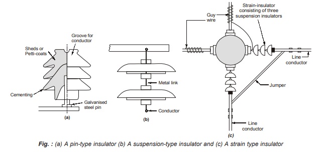
Types of Insulators
Various types of insulators used for overhead transmission and distribution lines are described as follows:
1. Pin-type insulator: The pin type insulator is secured to the cross-arm on the pole. There is a groove on the upper end of the insulator for housing the conductor. The conductor passes through this groove and is bound by the annealed wire of the same material as the conductor. These are used upto 50 kV only because they become uneconomical for higher voltages. The main advantage of a pin-type insulator is that it is cheaper. The modern practice is not to use it beyond 33 kV.
2. Suspension-type insulator: For high voltage (> 33 kV), it is a usual practice to use suspension type insulator. They consist of a number of porcelain discs connected in series by metal sinks in the form of a string. The conductor is suspended at the bottom end of this string while the other end of the string is secured to the cross-arm of the tower. The entire unit of suspension insulator is called string. Each unit of suspension type insulator is designed for low voltage (about 11 kV) and can be used for connecting them in series, the number depending on the working voltage. The suspension insulators are held in horizontal plane.
3. Strain-type insulators: When there is a dead end of the line, or there is a corner or a sharp curve, or the line crosses river etc., a strain-type insulator is used. For low-voltage line (upto 11 kV), “shackle insulators” can be used, but for higher voltage transmission lines “strain insulators” consisting of an assembly of “suspension type insulators” are used. The disc of strain-type insulators are employed in vertical plane. When the tension in lines is exceeding high, as at long river spans, two or more strings are used in parallel.
Below figures (a), (b) and (c) shows the arrangement of different insulators used in transmission and distribution system
String Efficiency
The voltage applied across the string of suspension insulators is not uniformly distributed across various units or discs. The disc nearest to the conductor has much higher potential than the other discs. This unequal potential distribution is undesirable and is usually expressed in terms of string efficiency.
Percentage string efficiency is defined as
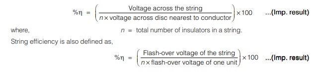
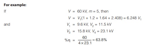
Remember: The string efficiency indicates the extent of wastage. Although the string efficiency can’t be made 100% but it’s value should be as high as possible.
Methods of Improving String Efficiency
Some of the methods which can be used to improve the string efficiency are as follows :
1. By using longer cross-arms : The value of string efficiency depends upon the value of m, i.e., ratio of shunt capacitance to mutual capacitance. The lesser the value of m, the greater is the string efficiency and more uniform is the voltage distribution. The value of m can be decreased by reducing the shunt capacitance. In order to reduce shunt capacitance, the distance of conductor from tower must be increased, i.e., longer cross-arms should be used.
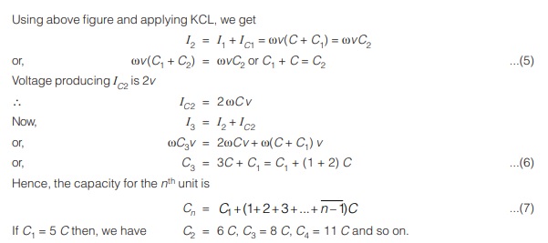
2. By grading the insulators : In this method, insulators of different dimensions are so chosen that each has different capacitance. The insulators are capacitance graded, i.e., they are assembled in the string in such a way that a top unit has the minimum capacitance, increasing progressively as the bottom unit (i.e., nearest to conductor) is reached. By proper grading of the capacitances, complete equality of voltage can be achieved. This is called “capacitance grading” shown below in figure.
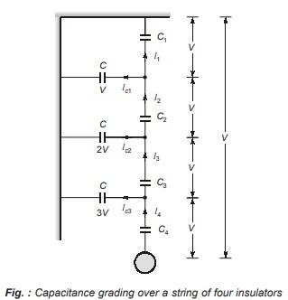
- Let the capacitance between the metal work and the power conductor be negligible.
- Let the mutual capacitance be C1 to C4 and the ground capacitance be C.
Note:
The disadvantage of capacitance grading is that it require a large number of different-sized insulator units which is uneconomical and impractical. In order to avoid these limitations, static shielding is used which employ identical insulator discs.
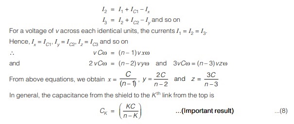
3. Static shielding: In this method, the voltage distribution is equalized by providing grading, or guard ring, in the form of a large metal ring surrounding the bottom unit and connected to the metal work at the bottom of this unit, and therefore to the line. This helps to cancel exactly the pin to tower charging currents so that the same current flows through the units of identical capacities to produce equal voltage drops across each unit as shown below in figure.
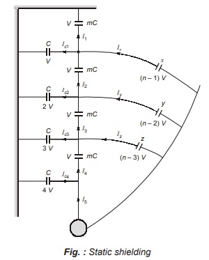
From above figure using KCL, we can write,
<< Previous | Next >>
Must Read: What is Power Systems?
Dear Aspirants,
Your preparation for GATE, ESE, PSUs, and AE/JE is now smarter than ever — thanks to the MADE EASY YouTube channel.
This is not just a channel, but a complete strategy for success, where you get toppers strategies, PYQ–GTQ discussions, current affairs updates, and important job-related information, all delivered by the country’s best teachers and industry experts.
If you also want to stay one step ahead in the race to success, subscribe to MADE EASY on YouTube and stay connected with us on social media.
MADE EASY — where preparation happens with confidence.
MADE EASY is a well-organized institute, complete in all aspects, and provides quality guidance for both written and personality tests. MADE EASY has produced top-ranked students in ESE, GATE, and various public sector exams. The publishing team regularly writes exam-related blogs based on conversations with the faculty, helping students prepare effectively for their exams.
