Bundled Conductors
What is Bundled Conductors?
A “bundled conductor” is a conductor made up of two or more sub-conductors, called sub-conductors, per phase in close proximity compared with the spacing between phases. In lines of 400 kV and higher voltages instead of going for a hollow conductor it is preferable to use more than one conductor per phase which is called bundling of conductors.
Below figure shows the arrangement of a bundled conductor consisting of two, three, or four sub conductors
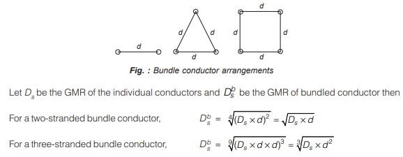
![]()
Remember
Difference between a composite and a bundled conductor:
The basis difference is that the sub-conductors of a bundled conductor are separated from each other by a constant distance varying from 0.2 m to 0.6 m depending upon designed voltage and surrounding conditions throughout the length of the line with the help of spacers whereas the wires of a composite conductor touch each other. The bundled conductors have filter material or air space inside so that the overall diameter is increased.
Various advantages of bundled conductor
- With the use of bundle conductors self GMD or GMR is increased which reduces the inductance of line and as a result, it decreases the inductive reactance. The lower inductance leads to a greater transmission capacity of the bundled conductor line.
- The bundle conductor lines transmit bulk power with reduced losses, thereby giving increased efficiency of transmission.
- Bundle conductor lines increases capacitance as (explained in next article) compared to single conductor line as a result of which charging current is increased, which helps in improving the power factor.
- Since surge impedance of line is : Zc = √L/C and bundle conductors decreases L and increases C therefore, bundle conductor lines have lower surge impedance compared to single conductor line which give rise to increase in maximum power transmission capability.
- Bundle conductors increases the critical disruptive voltage Vd as a result of which corona loss is reduced. (explained in next articles of corona).
CORONA
When the alternating potential difference between the two conductors of a transmission line is raised beyond a certain limit, a point is reached when a pale violet glow appears on the conductor surface, together with a slight hissing noise and a smell of ozone. This phenomenon is called “Corona”. The air particles around the conductor surface gets ionized and as a result corona occurs. This phenomenon is very much evident in transmission lines of 100 kV and above.
Effect of Corona
- Occurrence of violet glow around the conductor.
- Ozone and oxides of nitrogen are produced.
- It produces hissing noise.
- Corona induces harmonic current as a result of which charging current increases.
- Corona causes power loss in the line.
- There is radio interference.
Critical Disruptive Voltage (Vd)
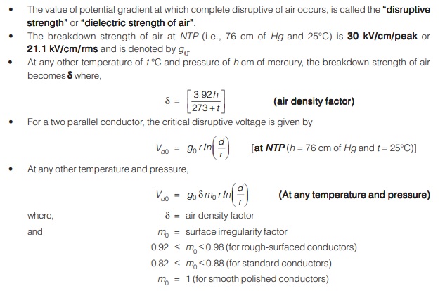
The minimum potential difference required between the conductors, to start ionization of air particles or the breakdown of the insulating properties of air occurs around the conductor surface and corona starts is known as “critical disruptive voltage” “critical disruptive voltage” denoted by Vd.
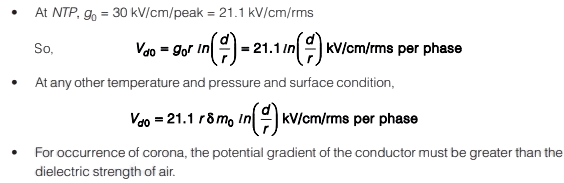
Disruptive Strength or Dielectric Strength of Air
Note:
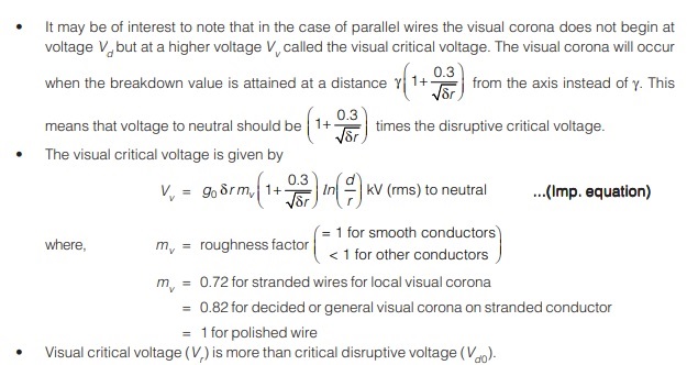
Visual Critical Voltage
- Visual critical voltage is defined as “the minimum voltage at which the visual corona beings”.
- When the voltage applied corresponds to the critical disruptive voltage, corona starts but it is not visible because the charged ions in the air must get some finite energy to cause further ionization by collisions.
Note:
If the surface of conductor is irregular, the corona does not start simultaneously on the whole surface but it takes place at different points of conductor which are pointed and this is called local corona.
Corona Power Loss
- The occurrence of corona results into loss of power, which reduces the efficiency of the transmission line, but don’t have appreciable effects on the voltage regulations.
- Corona loss under fair weather conditions is given by Peek’s formula as:
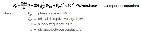
Remember:
- For a 500 kV transmission line with three-conductors per phase bundle, corona loss is small varying from 1 to 2 kW/km.
- Corona loss increases rapidly with bad weather, with frost being the worst situation.
- Due to several high-frequency harmonics in corona discharge, radio interference with the communication lines occur.
- Corona loss can be reduced by using large diameter conductors, hollow conductors and bundled conductors
Factors Affecting Corona Loss
The various factors affecting corona-loss in a transmission line are explained as follows.
Effect of Supply Frequency : From equation of corona loss, we have Pc α (f+ 25) . Therefore, corona loss increases with the increase in supply frequency i.e., corona loss for HVDC lines are less than that for EHV AC transmission lines. For a monopolar HVDC line, corona loss is minimum.
Effect of System Voltage : Corona loss occurs due to high electric field around the surface of the conductor. Therefore, higher the potential difference between the conductors (system voltage) higher is the electric field hence, higher is the power loss due to corona.
Effect of Conductivity of Air: Higher is the conductivity of air, higher is the number of ions and higher is the power loss due to corona. During rain and thunder storms, ion contents increases and therefore, atmosphere becomes more conducting and as the result corona loss increases.
Effect of Density of Air : Corona loss increases with the decrease in the density of air. Corona loss is more in hilly regions than that of a similar line in plains due to reduced value of d at higher altitudes.
Effect of Conductor Radius : With the increase in conductor radius, electric field intensity at the surface of conductor decreases resulting in reduced corona loss.
Effect of Conductor Surface : Corona loss is more for stranded conductor than for a solid conductor due to high potential gradient at the surface of stranded conductor. Corona loss is more for conductors having rough surfaces.
Effect of Atmospheric Conditions : Corona loss is more in rainy and bad atmospheric conditions such as fog, sleet and snowstorms.
Effect of Distance Between Conductors : Corona loss, Pc a = 1/√d Hence if distance between conductors is increased corona loss reduces.
Polarity of Conductors : For conductor of positive polarity, corona loss is more than for a conductor of negative polarity.
Bundling of Conductors : The effective diameter of the bundled conductor is much larger than that of the equivalent single conductor as a result of which corona loss is reduced.
Practical Importance of Corona
Corona acts as a safety valve for the conductor surface and decreases the impact of lightning surges on the surface of the conductor. It reduces the magnitude of high voltage steep fronted waves due to lighting or switching by partially dissipating them as corona loss.
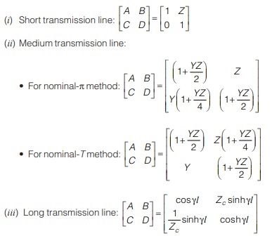
Transmission matrix:
Power Factor Improvement Methods
There are two method through which we can improve the power factor :
(i) Receiving end method :
(a) Shunt capacitor
(b) Shunt reactor
(c) Synchronous phase modifier (SPM)
(d) Series capacitor
(e) On-load tap changing transformer
(f) Booster transformer
(ii) Sending end method :
(a) Generator excitation control
<< Previous | Next >>
Must Read: What is Power Systems?
Dear Aspirants,
Your preparation for GATE, ESE, PSUs, and AE/JE is now smarter than ever — thanks to the MADE EASY YouTube channel.
This is not just a channel, but a complete strategy for success, where you get toppers strategies, PYQ–GTQ discussions, current affairs updates, and important job-related information, all delivered by the country’s best teachers and industry experts.
If you also want to stay one step ahead in the race to success, subscribe to MADE EASY on YouTube and stay connected with us on social media.
MADE EASY — where preparation happens with confidence.
MADE EASY is a well-organized institute, complete in all aspects, and provides quality guidance for both written and personality tests. MADE EASY has produced top-ranked students in ESE, GATE, and various public sector exams. The publishing team regularly writes exam-related blogs based on conversations with the faculty, helping students prepare effectively for their exams.