Concept of Critical Clearing Angle and Critical Clearing Time
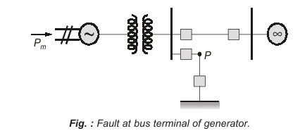
Let the system of figure shown above be operating with mechanical input Pm at a steady angle of δ0(Pm = Pe) as shown by the point a on the Pe – δ curve of figure shown below. When a three-phase fault occurs at the point P of the outgoing radial line, the electrical output of the generator instantly reduces to zero (Pe = 0) and the state point changes to b. The accelerating area A1 begins to increase and so does the rotor angle while the state moves along bc. At time tc corresponding to the rotor angle δc, the fault line is cleared by the opening of the line circuit breaker. The system now becomes healthy and transmits power Pe = Pmax⋅sin δ, i.e., the state point shifts to d on the original Pe – δ curve. The rotor now decelerate and the decelerating area A2 begins while the state point moves along de.
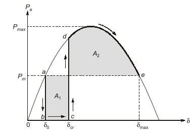
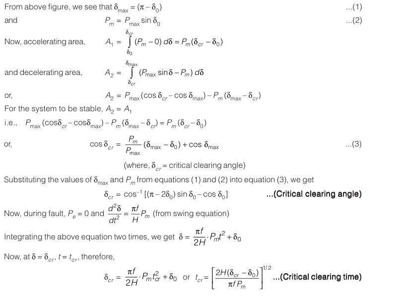
In above figure, δcr is called “critical clearing angle” and the time corresponding to it is called “critical clearing time”, tcr .
Note:
-
- The system will be stable if the circuit breaker clears the fault before the critical clearing angle δcr (or critical clearing time tcr ).
- Lower the value of δ0, higher the value of δcr therefore, higher will be the chances for the system to regain stability.
<< Previous | Next >>
Must Read: What is Power Generation?
Dear Aspirants,
Your preparation for GATE, ESE, PSUs, and AE/JE is now smarter than ever — thanks to the MADE EASY YouTube channel.
This is not just a channel, but a complete strategy for success, where you get toppers strategies, PYQ–GTQ discussions, current affairs updates, and important job-related information, all delivered by the country’s best teachers and industry experts.
If you also want to stay one step ahead in the race to success, subscribe to MADE EASY on YouTube and stay connected with us on social media.
MADE EASY — where preparation happens with confidence.
MADE EASY is a well-organized institute, complete in all aspects, and provides quality guidance for both written and personality tests. MADE EASY has produced top-ranked students in ESE, GATE, and various public sector exams. The publishing team regularly writes exam-related blogs based on conversations with the faculty, helping students prepare effectively for their exams.
