Comparisons between ZCS and ZVS Resonant Converters
ZCS and ZVS Resonant Converters
ZCS can eliminate the switching losses at turn-off and reduce the switching losses at turn-on. Because a relatively large capacitor is connected across the diode Dm, the inverter operation becomes insensitive to the diode’s junction capacitance. When power MOSFETs are used for ZCS, the energy stored in the device’s capacitance is dissipated during turn-on. This capacitive turn-on loss is proportional to the switching frequency. During turn-on, a high rate of change of voltage may appear in the gate drive circuit due to the coupling through the Miller capacitor, thus increasing switching loss and noise. Another limitation is that the switches are under high-current stress, resulting in higher conduction loss. It should, however, be noted that ZCS is particularly effective in reducing switching loss for power devices (such as IGBTs) with large tail current in the turn-off process.
By the nature of the resonant tank and ZCS, the peak switch current is much higher than that in a square wave. In addition, a high voltage becomes established across the switch in the off-state after the resonant oscillation. When the switch is turned on again, the energy stored in the output capacitor becomes discharged through the switch, causing a significant power loss at high frequencies and high voltages. This switching loss can be reduced by using AVS.
ZVS eliminates the capacitive turn-on loss. It is suitable for high-frequency operation. Without any voltage clamping, the switches may be subjected to excessive voltage stress, which is proportional to the load. For both ZCS and ZVS, the output voltage control can be achieved by varying the frequency. ZCS operates with a constant on-time control, whereas ZVS operates with a constant off-time control.
Static Kramer Drive
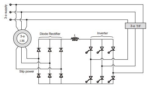
- In this method, slip power is getting transferred from rotor circuit to supply lines by adjusting its voltage and frequency values to the line values.
- As the slip power flows from rotor circuit to supply lines it is suitable for only subsynchronous speeds, i.e., below the synchronous speed.
NOTE: Sending end converter is in Rectification Mode (α < 90°) and receiving end converter is in Inversion mode (α > 90°).
Static Scherbius Drive
There are two configurations to obtain such a drive :
1. DC link scherbius drive
2. Cyclo converter scherbius drive
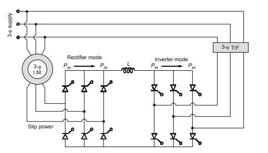
DC Link Scherbius Drive
- It consists of two phase controlled bridges, smoothening inductor and transformer.
- For sub synchronous speed control Phase Controlled Rectifier-I acts as rectifier (α < 90°). Phase Controlled Rectifier-II acts as line commutated inverter (α > 90°).
- For super synchronous speed control, P.C.R.-II acts as rectifier, P.C.R.-I will act as a line commutated inverter.
Cyclo Converter Scherbius Drive
It consists of a cyclo converter, which allows the power flow in both the directions by adjusting its frequency.
NOTE: Both the above scherbius drives are suitable for sub-synchronous as well as super synchronous speed.
<< Previous | Next >>
Must Read: What is Power Electronics?
Dear Aspirants,
Your preparation for GATE, ESE, PSUs, and AE/JE is now smarter than ever — thanks to the MADE EASY YouTube channel.
This is not just a channel, but a complete strategy for success, where you get toppers strategies, PYQ–GTQ discussions, current affairs updates, and important job-related information, all delivered by the country’s best teachers and industry experts.
If you also want to stay one step ahead in the race to success, subscribe to MADE EASY on YouTube and stay connected with us on social media.
MADE EASY — where preparation happens with confidence.
MADE EASY is a well-organized institute, complete in all aspects, and provides quality guidance for both written and personality tests. MADE EASY has produced top-ranked students in ESE, GATE, and various public sector exams. The publishing team regularly writes exam-related blogs based on conversations with the faculty, helping students prepare effectively for their exams.