1-φ Halfwave Rectifier with R-L Load and Free-wheeling Diode
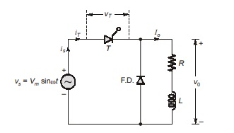
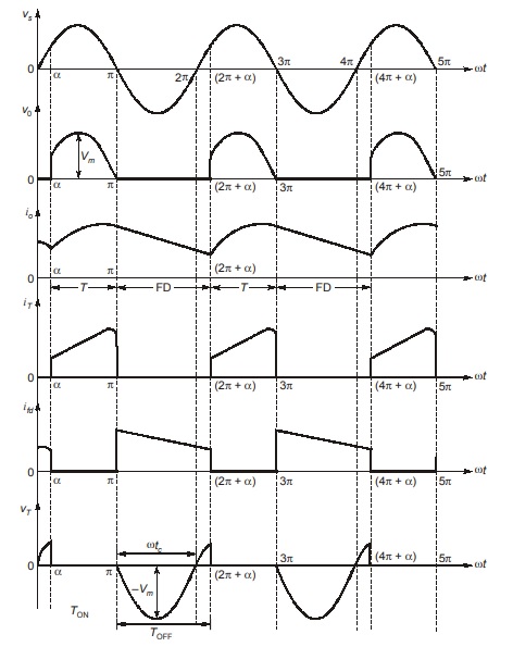
The SCR is triggered at ωt = α, the source voltage vs appears across load as vo. At ωt = π, the voltage vs becomes zero, just after this instant, freewheeling diode FD is forward biased.
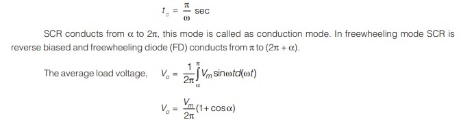
Assuming waveform, we can see that SCR is reversed biased for π radian (ωt = π to ωt = 2π), so circuit turn off time
Waveforms:
The advantage by using freewheeling diode are:
(i) input power factor is improved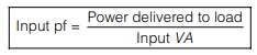
(ii) load current waveform is improved
(iii) as a result of (ii) load performance is better and
(iv) as energy stored in L is transferred to R during the freewheeling period, overall converter efficiency improves.
NOTE: FD prevents the load voltage V0 from becoming negative.
Principle of Operation of Step-up Choppers
When the average output voltage V0 greater than input voltage Vs , then the chopper is called step up chopper.
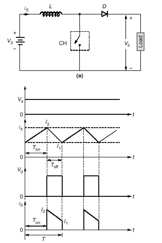
In this chopper, a large inductor L in series with source voltage Vs is essential as shown in figure. When the chopper CH is on, the closed current path is as shown in figure
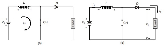
and inductor stores energy during Ton period. When the chopper CH is off, as the inductor current cannot die down instantaneously this current is forced to flow through the diode and load for a time Toff. As the current tends to decrease, polarity of the emf induced in L is reversed as shown.

<< Previous | Next >>
Must Read: What is Power Electronics?
Dear Aspirants,
Your preparation for GATE, ESE, PSUs, and AE/JE is now smarter than ever — thanks to the MADE EASY YouTube channel.
This is not just a channel, but a complete strategy for success, where you get toppers strategies, PYQ–GTQ discussions, current affairs updates, and important job-related information, all delivered by the country’s best teachers and industry experts.
If you also want to stay one step ahead in the race to success, subscribe to MADE EASY on YouTube and stay connected with us on social media.
MADE EASY — where preparation happens with confidence.
MADE EASY is a well-organized institute, complete in all aspects, and provides quality guidance for both written and personality tests. MADE EASY has produced top-ranked students in ESE, GATE, and various public sector exams. The publishing team regularly writes exam-related blogs based on conversations with the faculty, helping students prepare effectively for their exams.
