Types of Transformers
Generally, there are two types of transformers, the core type and shell type.
In core type the windings surround a considerable part of steel core as shown in fig. (a). In the shell type, the steel core surrounds a major part of the windings as shown in fig. (c). The vertical portions of the core are usually called limbs or legs and top and bottom portions are called the yoke. It means for single phase transformers core type has two-legged core whereas shell type has three-legged core.
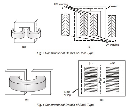
In core type transformer leakage flux is reduced by placing half of LV winding over one leg and other half over the second leg. For the HV winding over one leg and other half over the second leg. LV is placed adjacent to steel core and HV winding outside in order to minimise the amount of insulation required, as shown in fig. (b).
In shell type transformer LV and HV windings are wound over central limb and are interleaved or sandwiched as shown in fig. (d).
In core type flux has one path around the legs, while in shell type flux in central limb divides equally and returns through the two limb.
Comparison between core type and shell type transformers
| Core-type transformers | Shell-type transformers |
|
|
Testing of Transformers
These tests are carried out to determine the equivalent circuit parameters.
Open Circuit Test
- The purpose of this test is to determine the shunt branch parameters of the equivalent circuit of the transformer.
- Open circuit Test carried out at rated voltage and frequency to determine the core loss. Which then is treated as constant despite minor variations in voltage and frequency doing actual operation.
- This test is carried out with the instrument placed on the low voltage side while the high voltage side is kept open circuit. This is done because arranging rated voltage supply at the low voltage level is easier. Also, it is safer to work on the low voltage side.
- The primary copper loss is neglected because the no load current is very low so the primary impedance voltage drop is neglected at this low value of no load current, without much loss of accuracy. Hence, the wattmeter reading can be taken as equal to transformer core loss.
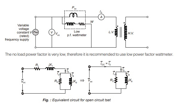
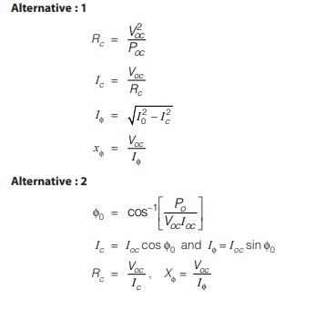
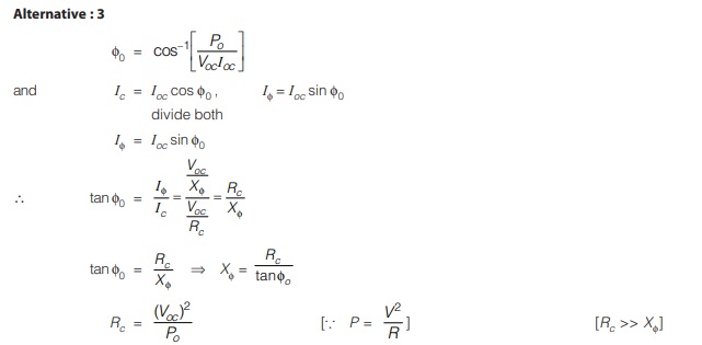
The parameters of equivalent circuit can be determined by using different alternatives, they are as follows :
From no load test:
Poc = no load input power, Voc = rated voltage, I0 = no load current
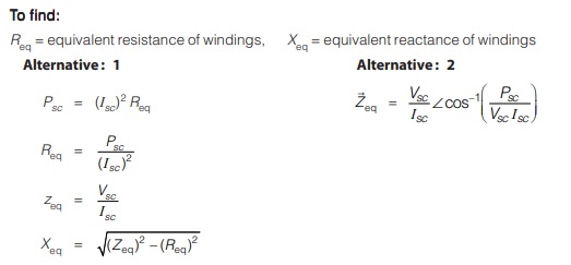
To find:
Rc = Core loss resistance, Xφ = Magnetising reactance
Short Circuit Test
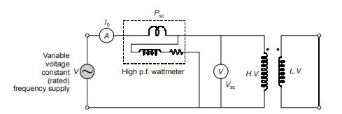
- This test serves the purpose of determining the series parameters of a transformer.
- Short circuit test is carried out on a transformer to determine the full load copper loss. Accordingly, this test is carried out at rated current and frequency although the requirement of rated frequency is not necessary.
- Instruments are placed on high voltage side with low voltage short circuited by a very thick wire of less resistance. In order to circulate full load current at short circuit, an input voltage of 8-10% of the rated voltage is usually sufficient and therefore the core loss during this test is ignored. Moreover, the no load current at such reduced voltage also becomes negligible and therefore can be ignored. This means that the exciting part of the equivalent circuit may not be considered during short circuit test. Hence, wattmeter can be taken to register only the ohmic losses in both the windings.
- The instruments are placed on high voltage side because this rated current on high voltage side is lower than low voltage side. Hence, ammeters, wattmeters and instruments transformers if any, of low current rating may be used.
From short circuit test:
Psc = full load input power,
Vsc = short circuit voltage,
Isc = full load current
Polarity Test
In determining the relative polarity of the two windings of a transformer the two windings are connected in series across a voltmeter. Generally, the ends of the LV winding are labelled with a small letter of the alphabet and are suffixed 1 and 2, while the HV winding are labelled by the corresponding capital letter and are suffixed 1 and 2 as shown in figure. HV winding terminals are marked with A1A2 and LV winding terminals are marked with a1a2
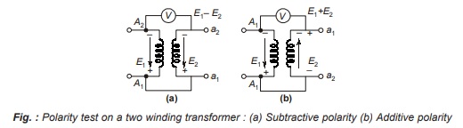
If the polarities of the windings are as marked on the fig. (a), the voltmeter should read E = E1 – E2. If it reads (E1 + E2), then it is called additive polarity shown in fig. (b). We don’t want additive polarity because these are subjected to high voltage stresses.
On account of these reasons, the polarity markings of one of the windings must be interchanged then after interchanging polarity voltmeter reads E1 – E2 is called subtractive polarity. Subtractive polarity is preferable to additive polarity.
Back to Back or Sumpner’s Test or Load Test
For large transformers, full load test is difficult, since it involves considerable waste of energy and a suitable load, capable of absorbing full load power, is not easily available. However, large transformers can be put on full load by means of Sumpner’s test. While open circuit test and short circuit tests on a transformer yield its equivalent circuit parameters, these cannot be used for the ‘heat run’ test, where the purpose is to determine the steady temperature rise if the transformer was fully loaded continuously; this is so because under each of these tests the power loss to which transformer is subjected is either the core-loss or copper-loss but not both.
In order to determine the maximum temperature rise, it is necessary to conduct a full-load test on a transformer or back to back test. It is also called Regenerative test or sumpner’s test. The back to back test on single phase transformers requires two identical transformers.
-
- The primary windings of the two transformers are connected in parallel and supplied at rated voltage and rated frequency.
- The secondaries are connected in series with their polarities in phase opposition which can be checked by the voltmeter V2. If the voltmeter Vab across a, b point reads zero, the secondaries are in series opposition and terminal a and b are use for test.
- If voltmeter Vab = sum of the two secondaries voltages. It means these are in the same phase. In order to bring them in phase opposition, terminals ad should be joined together to result in zero voltage across terminals bc.
- The total voltage across the two secondaries in series will be zero. There will be no current in the secondary windings. The transformers will behave as if their secondary windings are open circuited. Hence, the reading of wattmeter W1 gives the iron losses of both the transformers.
- Now a small voltage is injected in the secondary circuit by a regulating transformer excited by the main supply. The magnitude of the injected voltage is adjusted till the ammeter A2 reads full load secondary current, this current produces full load current to flow through the primary windings and will follow a circulatory path through the main bus bar.
- The reading of wattmeter W2 will not be not affected by this current. This wattmeter W2 gives the
full-load copper losses of the two transformers - This test can also be used for calculating the efficiency of a transformer
Parallel Operation of Transformer
Transformers are said to be connected in parallel when their primary windings are connected to a common voltage supply and their secondary windings are connected to a common load.
Reasons for Parallel Operation
The main reasons for operating transformers in parallel are as follows :
- For large loads it may be impractical or uneconomical to have a single large transformer.
- In substations the total load required may be supplied by an appropriate number of transformers of standard size. This reduces the reserve capacity of the substation.
- There is a scope of future expansion of a substations to supply a load beyond the capacity of the transformers already installed.
- If there is a breakdown of a transformer in a system of transformers connected in parallel, there is no interruption of power supply for essential services. Similarly, when a transformer is taken out of service for its maintenance and inspection, the continuity of supply is maintained.
Conditions to be satisfied for parallel operation
(A) For 1-φ and 3-φ transformer transformer
- Same polarity (must).
- Same voltage ratio and voltage rating (must).
NOTE : Small difference in voltage rating may be permitted if unavoidable.
- Same p.u. impedance for proportional load sharing (desirable) (Name plate zp.u.).
- Same X/R ratio of same p.f. operation (desirable).
(B) For 3-φ transformers only
- Same phase sequence (must).
- Zero phase difference (must).
(This means that transformer belonging to the same phasor group may along paralleled).
Dear Aspirants,
Your preparation for GATE, ESE, PSUs, and AE/JE is now smarter than ever — thanks to the MADE EASY YouTube channel.
This is not just a channel, but a complete strategy for success, where you get toppers strategies, PYQ–GTQ discussions, current affairs updates, and important job-related information, all delivered by the country’s best teachers and industry experts.
If you also want to stay one step ahead in the race to success, subscribe to MADE EASY on YouTube and stay connected with us on social media.
MADE EASY — where preparation happens with confidence.
MADE EASY is a well-organized institute, complete in all aspects, and provides quality guidance for both written and personality tests. MADE EASY has produced top-ranked students in ESE, GATE, and various public sector exams. The publishing team regularly writes exam-related blogs based on conversations with the faculty, helping students prepare effectively for their exams.
