Difference between Induction Motor and Transformer
Induction Motor Vs Transformer
| Transformer | Induction Motor | |||||
| (i) Electrical to electrical conversion through high permeability core. |
(i) Electrical to mechanical conversion through air-gap. |
|||||
| (ii) Requires less magnetizing current, i.e., 2% to 6% of full load. | (ii) Requires more magnetizing current, i.e., 30% to 50% of full load current. | |||||
| (iii) Operates at low lagging power factor on no-load. | (iii) Operate at much low lagging power factor on no-load. | |||||
| (iv) Induced emf depends on turns ratio. | (iv) Induced emf depends on turn ratio, only at standstill. But changes with speed under running. | |||||
| (v) Primary and secondary frequency is same. | (v) At standstill only, stator and rotor frequencies are same but significantly changes with speed. | |||||
| (vi) Secondary is not shorted. | (vi) Rotor is essentially short circuit. | |||||
| (vii) Primary and secondary winding are concentrated. | (vii) Winding is distributed. | |||||
| (viii) Less leakage flux and less leakage reactance. | (viii) More leakage flux and less leakage reactance. | |||||
Magnetic Locking (Cogging)
The phenomenon of magnetic locking between stator and rotor teeth is called cogging or teeth locking. If stator slots are equal to rotor slot or multiple rotor slot then magnetic locking occurs. Due to this phenomenon 3-φ cage induction motor fails to start. While full voltage is applied.
The reluctance of the magnetic path is minimum when the stator and rotor teeth face each other. Under this condition there is magnetic locking between stator and rotor teeth.
Either slots of stator,
s1 = slots of Rotor s2.
s1 = ks2 (Integral multiple of each other)
k → Integer
The variation in reluctance as a function of space is pronounced and results in strong alignment forces. Let at the time of starting stator teeth and rotor teeth are aligned. When the rotor tries to rotate, reluctance in the path of flux increases hence flux trying to keep stator teeth and rotor teeth align to follow low reluctance path. If starting torque is very small, then alignment force per pole is more than the starting torque. This is called cogging phenomena.
Alignment force > Tst
The cogging phenomena occurs in SCIM as starting torque is low. In order to reduce or eliminate cogging the number of stator slots are never made equal to or have an integral ratio. Cogging can also be reduced by using skewed rotor.
Crawling
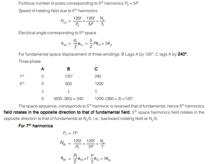
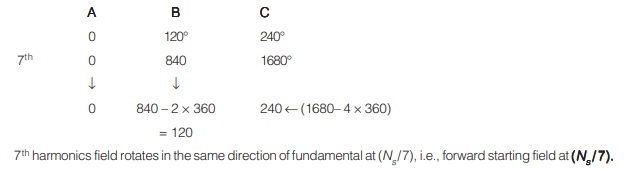
Certain combination of stator and rotor slots (not necessarily) integral multiple) leads to certain space harmonics in mmf wave. e.g., if 5th and 7th space harmonics are present in mmf wave due to certain combination of slots s1 and s2.
From the observation and graph. Due to the presence of seventh harmonics in flux torque, the load torque curve intersects the motor torque-speed characteristic at point A. Since the seventh harmonic flux torque curve has negative slope.
Due to this, the motor torque falls below the load torque. At this stage the motor will not accelerate upto its normal speed but will remain running at a speed which is nearly (1/7) of its normal speed and operating point would be A. This tendency of the motor to run at a stable speed low as 1/7th of the normal speed Ns and being unable to pickup its normal speed is known as crawling of the motor. Crawling can be reduced by reducing fifth and 7th harmonics. This can be done by using a chorded (or short pitched) winding.
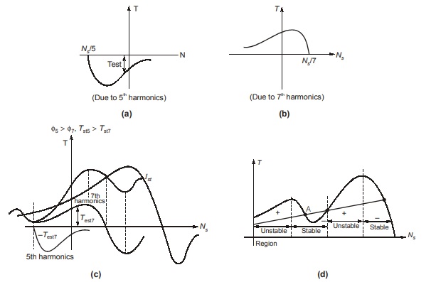
Due to the presence of harmonics there is additional stable region at a speed near Ns/7. In torque speed characteristics for a particular load torque as shown the motor runs stably at reduced speed N1<<N0 very less than rated No.
Note:
Corresponding to triplen harmonics 3, 9, 15, 21. The wdg is not balanced means phase difference is not 120°. Hence they will not generate any rotating field. Cogging and crawling are much less prominent in wound rotor motors because of there higher starting torques.
Double Cage Rotor
When high torques are required during starting double cage rotors are used. The arrangement of two cages for production of large starting torque is shown in figure. 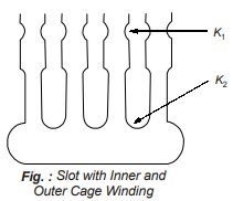
In this figure, cage K1 is close to the periphery of the rotor (outer cage) and has a high resistance. The winch cage K2 has a low resistance, but is set deeply in slots having a considerable leakage flux on account of long narrowed slit. Thus the outer cage has a high resistance together with a low reactance normal to an ordinary cage winding, while the inner cage has a low resistance and large reactance. At starting, the leakage reactance of the inner cage is large enough to cause the rotor current to flow chiefly in outer cage, the high resistance of which produces considerable I2R losses and consequently good starting torque.
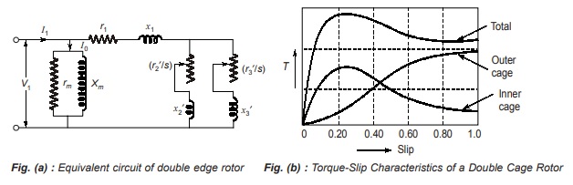
When the speed is normal, the reactance of both cages is almost negligible, so that the rotor current is carried by two cages in parallel giving a low effective resistance. The total torque is the summation of two individual torques and it will be clear that by varying the several resistance and reactances, a wide range of operational characteristics is possible. Below given figs. (a) and (b) show the equivalent circuit and torque-slip characteristics respectively for a double cage motor.
Single-Phase Induction Motors
If one line of a three phase induction motor is opened while the motor is running with moderate or light load, it is found that the motor continues to run though at slightly lower speed. This condition is known as single phase operation. Opening of one line (phase) leaves the equivalent of a single phase connected to the stator. In other words, a 3-phase induction motor has became a single phase motor.
A single phase induction motor is similar to a 3-phase squirrel cage induction motor in physical appearance. The rotor of a single phase squirrel cage motor is essentially the same as that employed in 3-phase induction motors and needs no further description. There is uniform air gap between stator and rotor but no electrical connection between them (stator and rotor). Except for shaded-pole types, the stator core is also very similar. A single phase motor can be wound for any even number of poles, two. four, and six being most common. Like three-phase machines, adjacent poles have opposite magnetic polarity and synchronous speed equation also applies.
(Ns = 120f/P)
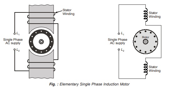
An elementary single phase induction motor is shown below in figure (Elementary Single Phase Induction Motor).
Working:
When the stator winding of a single phase induction motor is connected to single phase ac supply, a magnetic field is developed, whose axis is always along the axis of stator coils. With alternating current in the fixed stator coil the mmf wave is stationary in space but pulsates in magnitude and varies sinusoidally with time. Currents are induced in the rotor conductors by transformer action, these currents being in such a direction as to oppose the stator mmf. Thus the axis of the rotor mmf wave coincides with that of the stator field, the torque angle is, therefore, zero, and no torque is developed at starting. However, if the rotor of such a motor is given a push by hand or by another means in either direction, it will pick up the speed and continue to rotate in the same direction developing operating torque. Thus a single phase induction motor is not self starting and needs special starting means.
Single phase induction motors suffer from several drawbacks such as low overload capacity, low efficiency, low power factor etc.
The peculiar behaviour, mentioned above, of a single phase induction motor may be explained by any one of the following two theories
1. Double revolving field theory
2. Cross-field theory
Both theories have their own advantages and fields of application. They ultimately lead to the result that are approximately same.
Transformers & Induction Machines for GATE & UPSC ESE
Dear Aspirants,
Your preparation for GATE, ESE, PSUs, and AE/JE is now smarter than ever — thanks to the MADE EASY YouTube channel.
This is not just a channel, but a complete strategy for success, where you get toppers strategies, PYQ–GTQ discussions, current affairs updates, and important job-related information, all delivered by the country’s best teachers and industry experts.
If you also want to stay one step ahead in the race to success, subscribe to MADE EASY on YouTube and stay connected with us on social media.
MADE EASY — where preparation happens with confidence.
MADE EASY is a well-organized institute, complete in all aspects, and provides quality guidance for both written and personality tests. MADE EASY has produced top-ranked students in ESE, GATE, and various public sector exams. The publishing team regularly writes exam-related blogs based on conversations with the faculty, helping students prepare effectively for their exams.
