DC Machine Construction
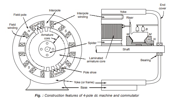
A DC machine has two main parts stator and rotor. The stator of the machine does not move, i.e., stationary and normally is the outer part of the machine. The rotor is free to move and normally is the inner part of the machine. Slots are cut on the inner periphery of the stator and outer periphery of the rotor, while conductors are placed in these slots of rotor and stator. The winding in which voltage is induced is called the armature winding and the winding through which a current is passed to produce the main flux is called the field winding.
Stator of a d.c. machine consists of yoke (or frame), field windings, interpoles, compensating winding, brushes and end covers. Rotor consists of armature core, armature winding, commutator and shaft. Stator components are described first.
Yoke :
It has two functions :
- it provides path for the pole flux φ and carries half of it, i.e., φ/2;
- it provides mechanical support to the whole machine. Since the flux carried by yoke is stationary (i.e., constant), it is not laminated. As stated before, cast iron is used for small d.c. machines and fabricated steel for large d.c. machines. In case d.c. motor is to be operated through a power-electronics converter, the yoke is laminated to reduce the eddy-current losses.
Field Poles :
Field pole consists of pole core and pole shoe. The pole core is made from cast steel but the pole shoe is laminated and fixed to the pole core appropriately.
Both pole core and pole shoe are made from thin laminations of sheet steel to reduce the eddy-current losses. The laminated pole is welded or bolted to the yoke.
Field (or Exciting) winding :
The pole is excited by a winding wound around the pole core. This winding, called field or exciting winding, is prepared from copper. The number of turns and cross-section of field winding depend upon the type of d.c. machine as under :
- For d.c. shunt machine large number of turns of small cross-section are used.
- For d.c. series machine, small number of turns of large cross-section are used.
- For d.c. compound machine, both shunt (thin wire) and series (thick wire) field windings are used.
Interpoles :
These are fixed to the yoke in between the main poles of a d.c. machine. These are usually tapered with sufficient sectional area at the root to avoid magnetic saturation. The interpole winding, consisting of a few turns of thick wire, is connected in series with the armature so that its magnetomotive force is proportional to armature current.
Compensating windings :
These windings are placed in the slots cut in the pole faces of a d.c. machine. Compensating winding is also connected in series with the armature circuit.
Brushes :
Brushes are housed in box-type brush holders attached to the stator end cover or the stator yoke. A small spring keeps the brushes pressed on to the commutator surface. The brush pressure on the commutator surface must be carefully adjusted. Too small a brush pressure may lead to excessive arcing between the brush-commutator contact. If the brush pressure is too high, it may cause excessive wear of the commutator surface and the brushes.
Brushes are made of carbon for small d.c. machines, electrographite for all d.c. machines and copper graphite for low-voltage high-current d.c. machines
Rotor components are now described below :
Armature core :
It serves the twin purpose of :
- Housing the armature coils in the slots and,
- Providing the low-reluctance path to the magnetic flux φ/2. It is made from 0.35 to 0.50 mm thick laminations of silicon steel to keep down the iron losses.
Armature winding :
The armature winding is made from copper. It consists of large number of insulated coils, each coil having one or more turns. The coils are usually former wound. These are placed in slots and appropriately connected in series and parallel depending upon the type of winding required. There are basically two winding types :
(i) Lap winding.
(ii) Wave winding.
Commutator :
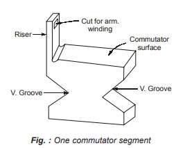
It is of cylindrical structure. It is built up of wedge-shaped segments of high conductivity hard-drawn copper to reduce its wear and tear. Segments are insulated from each other by 0.8 mm thick mica sheets. The segments are tapered as shown in fig. so that their assembly results in circular shape. Hub H and ring R are insulated from commutator segments by mica sheet M and V-shaped so as to prevent the segments from flying out due to centrifugal forces. Each commutator segment, has a riser where conductors from the armature winding are connected.
Shaft :
On mature shaft are mounted
(i) hub H of commutator
(ii) spider in big machines or armature core in small machines and
(iii) bearings.
End covers are connected to the yoke on one side and to the bearings and shaft on the other side
Electric Braking of D.C. Motors
Electric braking is usually employed in applications to stop a unit driven by motors in an exact position or to have the speed of the driven unit suitably controlled during its deacceleration. In applications requiring frequent, quick, accurate or rapid emergency stops, electric braking is used. For example, in suburban electric trains quick stops are required. Electric braking allows smooth stops with out any inconvenience to passengers.
When a loaded hoist is lowered, electric braking keeps the speed within safe limits, otherwise, the drive speed will reach dangerous values.
When a train goes down a steep gradient, electric braking is employed to hold the train speed within safe limits. Similarly, in applications involving other active loads, electric braking is very commonly used.
The braking force can also be obtained by using mechanical brakes.
Disadvantages of Mechanical Braking:
The following are the main disadvantages of mechanical braking:
- It requires frequent maintenance and replacement of brake shoes.
- Braking power is wasted as heat.In spite of the disadvantages, mechanical braking is used along with electric braking to ensure reliable operation of the drive. Mechanical brakes are also used to hold the drive at standstill because many braking methods do not produce torque at standstill.
Types of Electric Braking
There are three types of braking a dc motor:
1. Regenerative braking
2. Dynamic braking or rheostatic braking
3. Plugging or reverse current braking
Regenerative Braking
It is a form of braking in which the kinetic energy of the motor and its driven machinery is returned to the power supply system. This type of braking is possible when the driven load forces the motor to run at a speed higher than its no-load speed with a constant excitation. Under this condition, the motor back emf Eb is greater than the supply voltage V, which reverse the direction of motor armature current. The machine now begins to operate as a generator and the energy generated is supplied to the source.
Regenerative braking can also be carried out upto very low speeds if the motor is connected as a separately excited generator and excitation is increased as the speed is reduced, so that
![]()
are satisfied and the motor does not enter into saturation on increasing excitation.
Regeneration is possible with a shunt and separately excited motors and with compound motors with weak series compounding. Regenerative braking is used specially where more frequent braking or slowing of drives is required. It is most useful in holding a descending load of high potential energy at a constant speed. For example, regenerative braking is used to control the speed of motors driving loads such as electric locomotives, elevators, cranes and hoists. While descending, the load in this operation acts as the prime mover by virtue of its potential energy. The motor acts as a generator. The generated power is thus returned to the supply. The returned power is available for other devices operating from the same source of supply. Regenerative braking cannot be used for stopping the motor. It is used for controlling the speed above the no-load speed of the motor driving the descending loads or overhauling loads.
The necessary condition for regeneration is that the back emf Eb should be greater than the supply voltage so that the armature current is reversed and the mode of operation changes from motoring to generating.
Regenerative Braking in dc Shunt Motors:
Under normal operating conditions the armature current is given by
– Ia = V-Eb/Ra
When the load (such as lowering of load by a crane, hoist or lift) causes the motor speed to be greater than the no-load speed, the back emf Eb becomes greater than the supply voltage V. Consequently, armature current Ia becomes negative. The machine now begins to operate as a generator.
Regenerative Braking in dc Series Motors
In case of a dc series motor an increase in speed is followed by a decrease in the armature current and field flux. The back emf Eb cannot be greater than the supply voltage. Regeneration is not possible in a plain dc series motor since the field current cannot be made greater than armature current. However, in applications such as traction, elevators, hoists etc., where dc series motors are used extensively, regeneration may be required. For example, in an electro-locomotive moving down a gradient, a constant speed may be necessary and in hoist drives the speed is to be limited whenever it becomes dangerously high. One commonly used method of regenerative braking of the dc series motor is to connect it as a shunt motor. Since the resistance of the field winding is low, a series resistance is connected in the field circuit to limit the current within the safe value.
Dynamic Braking or Rheostatic Braking
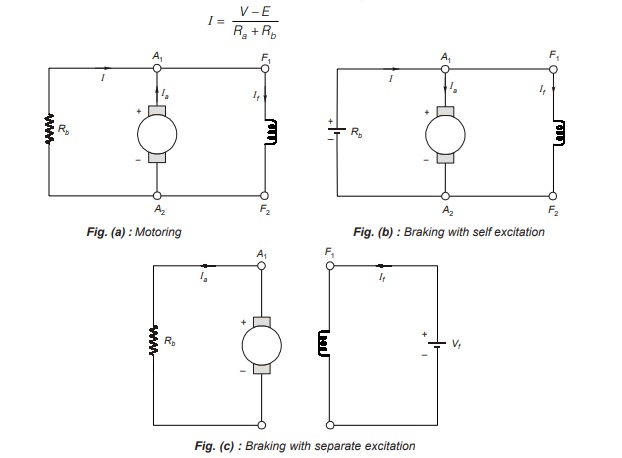
In dynamic braking, the dc motor is disconnected from the supply and a braking resistor Rb is immediately connected across the armature. The motor now works as a generator, producing the braking torque.
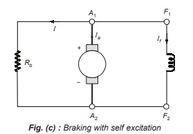
For the braking operation, the separately excited (or shunt) motor can be connected either as a separately excited generator, where the flux is kept constant, or it can be connected as a self-excited shunt generator, with the field winding in parallel with the armature. Fig. (b) shows the dynamic braking of separately excited dc motor. Fig. (c) shows the dynamic braking of a dc shunt motor.
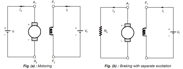
This method is also called rheostatic braking because an external braking resistance Rb is connected across the armature terminals for electric braking. During electric braking when the motor works as a generator, the kinetic energy stored in the rotating parts of the motor and connected load is converted into electric energy. It is dissipated as heat in the braking resistance Rb and armature circuit resistance Ra
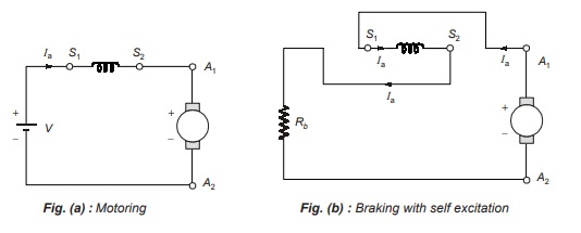
For dynamic braking, the series motor is disconnected from the supply, the field connections are reversed and the motor is connected in series with a variable resistance Rb as shown below in figure (b).
The field connections are reversed to make sure that the current through the field winding flows in the same direction as before (that is from S1 to S2) in order that the back emf Eb aids the residual flux. The machine now works as a self-excited series generator.
The braking operation is slow with self excitation. When quick braking is required, the machine is connected for the separate excitation, and a suitable resistance is connected in series with the field to limit the current to a safe value.
Dynamic braking is an inefficient method of braking, because all the generated energy is dissipated as heat in resistances.
Plugging or Reverse Current Braking
In this method the armature terminals (or supply polarity) of a separately excited (or shunt) motor when running are reversed. Therefore, the supply voltage V and the induced voltage Eb (back emf) will act in the same direction. Thus during braking the effective voltage across the armature will be (V + Eb) which is almost twice the supply voltage. The armature current is reversed and a high braking torque is produced. In order to limit the armature current to a safe value, an external current-limiting resistor Rc is connected in series with the armature.
I = -(V+Eb)/Ra+Rc
For braking a series motor either the armature terminals or field terminals (but not both) are reversed. Reversing of both given only normal working operation.
The braking torque is not zero at zero speed. When used for stopping a load, the motor must be disconnected from the supply at or near zero speed, otherwise, it will speed up in the reverse direction. Centrifugal switches are used to disconnect the supply.
Plugging is a highly inefficient method of braking because in addition to the power supplied by the load, power supplied by the source is wasted in resistances.
Plugging is commonly used in controlling elevators, rolling mills, printing presses and machine tools etc.
Present–Day Uses of D.C. Machines
At present time bulk of electric energy is generated in the form of alternating current. Hence the use of d.c. generators is very limited. They are mainly used in supplying excitation of small and medium range alternators. For industrial applications of d.c. like electrolytic processes, welding processes and variable speed motor drives, the present trend is to generate a.c. and then to convert a.c. into d.c. by rectifiers. Thus, dc generators have generally been superseded by rectified as supplies for many applications.
Direct current motors are very commonly used as variable-speed drives and in application s where severe torque variations occur
The main applications of the three types of d.c. motors are given below:
- Series Motors: These motors are used where high starting torque is required and speed can vary, for example, traction, cranes, etc.
- Shunt Motors: These motors are used where constant speed is required and starting conditions are not severe, for example, lathes, centrifugal pumps, fans, blowers, conveyors, lifts etc.
- Compound Motors: These motors are used where high starting torque and fairly constant speed is required, for example, presses, shears, conveyors, elevators, rolling mills, heavy planers etc.
Small d.c. machines (in fractional kilowatt rating) are used primarily as control devices such as techogenerators for speed sensing and servomotors for positioning and tracking.
Previous Year Question for GATE | DC Machines
Dear Aspirants,
Your preparation for GATE, ESE, PSUs, and AE/JE is now smarter than ever — thanks to the MADE EASY YouTube channel.
This is not just a channel, but a complete strategy for success, where you get toppers strategies, PYQ–GTQ discussions, current affairs updates, and important job-related information, all delivered by the country’s best teachers and industry experts.
If you also want to stay one step ahead in the race to success, subscribe to MADE EASY on YouTube and stay connected with us on social media.
MADE EASY — where preparation happens with confidence.
MADE EASY is a well-organized institute, complete in all aspects, and provides quality guidance for both written and personality tests. MADE EASY has produced top-ranked students in ESE, GATE, and various public sector exams. The publishing team regularly writes exam-related blogs based on conversations with the faculty, helping students prepare effectively for their exams.
