Quality Factor Meter (Q Meter)
A quality factor meter is an instrument which is used to measure the value of storage factor Q directly and measuring the characteristics of coils and capacitors. It is used in laboratories for testing radio frequency coils.
Principle of Operation
• Q-meter works on the principle of series resonance.
• Figure given below shows a series RLC circuit.
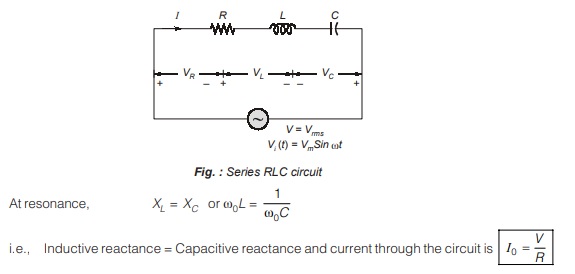
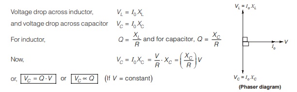
Therefore, if the input voltage is constant, voltage across the capacitor is magnified Q times and a voltmeter can be connected across the capacitor which can be calibrated to read the value of Q directly.
Practical Circuit of Q-meter
Below figure shows a practical Q-meter
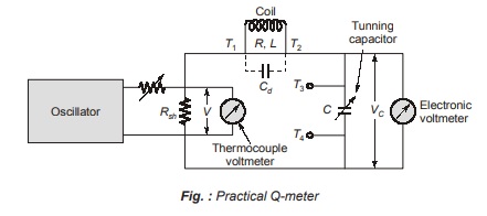
It consists of a variable radio frequency oscillator which delivers a current to a low shunt resistance, Rsh which is order of 0.02 Ω (typical value). The voltage is measured by a thermocouple voltmeter. A calibrated standard variable capacitor C is used for getting the series resonance condition. An electronic voltmeter is connected across this capacitor C. The coil under test is connected between the terminals T1 and T2.
Applications of Q-meter
1. Measurement of Quality Factor of Test Coil
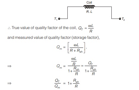
The test coil is connected between terminals T1 and T2. The oscillator is set to the desired frequency and then, the capacitor, C is adjusted to get the series resonance condition.
Let the coil resistance and inductance be R and L respectively,
Note:
To get minimum error, the shunt resistance should be very small. As Rsh of the order of mΩ therefore, QT ≈ Qm.
Therefore, the true value of quality factor of the coil is obtained when Rsh is maintained in mΩ range (can be neglected).
2. Measurement of Unknown Capacitance
- For measurement of unknown capacitance, the test capacitance CT is connected in parallel with the known value of the capacitance, C between the terminals T3 and T4.
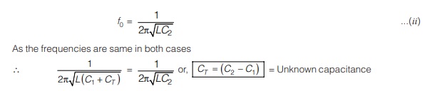
- By adjusting the capacitor C to C1, the circuit is resonated to a frequency, f0.
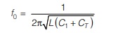
- Now, the test capacitance across T3 and T4 is removed and the capacitor C is readjusted to C2 to get the same value of resonant frequency
3. Measurement of Unknown Inductance

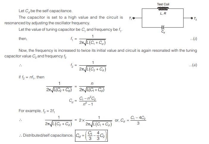
4. Measurement of Self Capacitance
5. Measurement of Unknown Resistance

Dear Aspirants,
Your preparation for GATE, ESE, PSUs, and AE/JE is now smarter than ever — thanks to the MADE EASY YouTube channel.
This is not just a channel, but a complete strategy for success, where you get toppers strategies, PYQ–GTQ discussions, current affairs updates, and important job-related information, all delivered by the country’s best teachers and industry experts.
If you also want to stay one step ahead in the race to success, subscribe to MADE EASY on YouTube and stay connected with us on social media.
MADE EASY — where preparation happens with confidence.
MADE EASY is a well-organized institute, complete in all aspects, and provides quality guidance for both written and personality tests. MADE EASY has produced top-ranked students in ESE, GATE, and various public sector exams. The publishing team regularly writes exam-related blogs based on conversations with the faculty, helping students prepare effectively for their exams.
