Maxwell’s Inductance Bridge
Maxwell’s Inductance Bridge measures an inductance by comparison with a variable standard self inductance. The bridge circuit arrangement with the phasor diagram are shown below in figure.
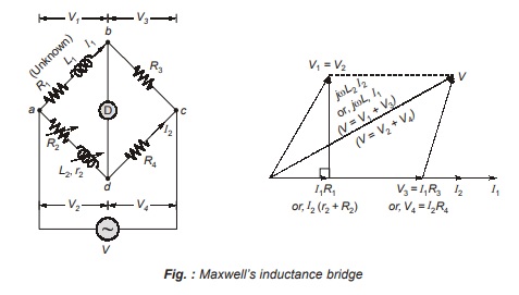
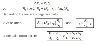
Under balance condition:
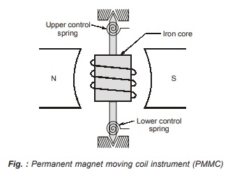
Permanent Magnet Moving Coil (PMMC) Instrument
The constructional features of PMMC instrument are shown below in figure which is very much similar to d’Arsonval type of galvanometer.
• Principle of operation: The moving coil consists of number of turns of fine wire and current is passed through it. The iron core provides a flux path of low reluctance which creates a strong magnetic field. The moving coil carries current I and produces a deflecting torque proportional to current. When the deflecting torque (proportional to I) is equal to the control torque (proportional to θ), the pointer indicates the measured value of current or voltage. Eddy current damping is given to damped out the oscillation at steady state point
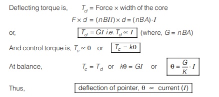
Equation of Torque:
Let
d = width of the core
l = length of the core
n = number of turns of the coil
I = current through moving coil
K = spring constant
θ = deflection of moving coil
B = Magnetic flux density
A = Area of cross section of core = d × l
Remember:
- The PMMC instruments measures the DC quantity of current.
- If a pure ac signal is passing through PMMC then, it reads zero value.
- If the output of half wave rectifier passes through PMMC then, it reads the average value of
the half wave rectifier output (i.e., Im /π = Iavg). - If the output of full wave rectifier is passed through PMMC, then, it will read average value
of the full wave rectifier output (i.e., 2Im/π). - If a current of i = (I0 + I1 sin ωt + I2 sin 2ωt + ….) is passed through PMMC then, it reads I0.
- The control torque is provided by the ribbon suspension (or spring) which eliminates bearing friction.
- Type of damping used is eddy current damping produced by the movement of aluminium former moving in the magnetic field of permanent magnet.
- It has a linear scale.
- The accuracy of the instrument is higher due to higher torque to weight ratio of the instrument.
- The power consumption is very low.
- Error due to stray magnetic fields are less.
Disadvantage of PMMC Instruments
• The magnetic field produced is affected by the surrounding temperature which causes error in reading.
• The instrument is used to measure dc only.
• It is costly compared to moving iron instruments.
• It can measure current upto 50 mA and voltage upto 100 mV only.
Enhancement of PMMC Meters
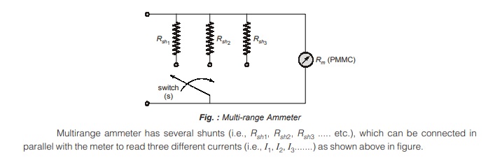
For reading higher range of current and voltage, Ammeter shunts and voltmeter multiplier are used respectively.
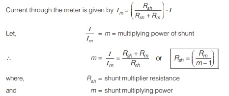
Ammeter Shunts
When high current is to be measured, most of the current is bypassed through a low resistance called a “shunt”.
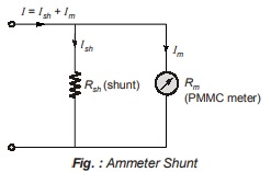
Effect of Temperature Changes in Ammeters
If the surrounding temperature increases then, the meter resistance, Rm increases which causes decrease in the current through meter (Im) so that the meter reads errorneous value.
To compensate the temperature effect a resistance called “swamp resistance” is added in series with the meter. The swamp resistance is made up of mangnin which has low value of temperature coefficient.
The shunt resistance after addition of swamp resistance is given by
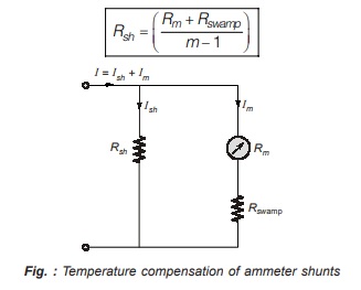
Multi-range Ammeter
The current range of a d.c. ammeter can be extended by a number of shunts, selected by a range switch.
Such a meter is called “multirange Ammeter”. A multirange ammeter is shown below in figure.
<< Previous | Next >>
Must Read: What are the Electrical and Electronics Measurements?
Dear Aspirants,
Your preparation for GATE, ESE, PSUs, and AE/JE is now smarter than ever — thanks to the MADE EASY YouTube channel.
This is not just a channel, but a complete strategy for success, where you get toppers strategies, PYQ–GTQ discussions, current affairs updates, and important job-related information, all delivered by the country’s best teachers and industry experts.
If you also want to stay one step ahead in the race to success, subscribe to MADE EASY on YouTube and stay connected with us on social media.
MADE EASY — where preparation happens with confidence.
MADE EASY is a well-organized institute, complete in all aspects, and provides quality guidance for both written and personality tests. MADE EASY has produced top-ranked students in ESE, GATE, and various public sector exams. The publishing team regularly writes exam-related blogs based on conversations with the faculty, helping students prepare effectively for their exams.
