Error in Electrodynamometer Wattmeters
The error occurring in electrodynamometer wattmeters are explained as under :
1. Error due to Connection
There are two methods of connecting a wattmeter in a circuit as shown in fig. (a) and (b). Due to the power loss in pressure coil and current coil, there is error in the measurement of power.
The wattmeter measures the power consumed by the load plus the power loss in c.c. or p.c.
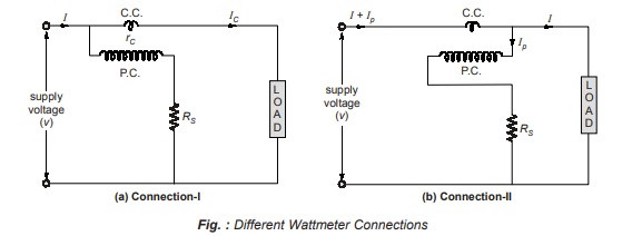
Connection-I:
Let rc = resistance of current coil, Ic = current through current coil = load current
Here, p.c. is connected on the supply side.
Here, wattmeter measures the power in its current coil in addition to the power consumed by load
Note:
- For low value of load current, Ic will be low.
- Therefore, Connection-I is suitable for the measurement of power for low value of load current.
Connection-II:
Let the resistance of the c.c. be very small, IP = current through the pressure coil

Note:
Where I is high then, IP will be low and error will be less.
• Therefore, Connection-II is preferred when the load current is higher.
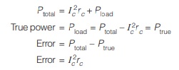
• When error in Connection-I and II are equal then,
I c2rc = V2/Rs
Error due to Pressure Coil Inductance
Fig. (a) and (b) shows an electrodynamometer wattmeter without pressure coil inductance and with pressure coil inductance.
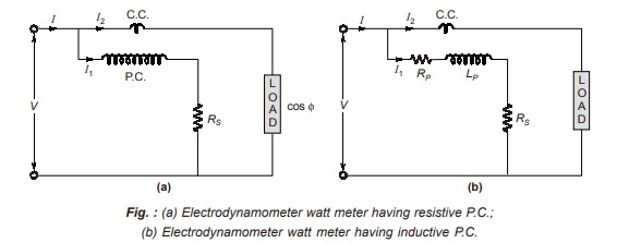
Without Inductance in p.c.:
Here, current I1 will be in phase with applied voltage V
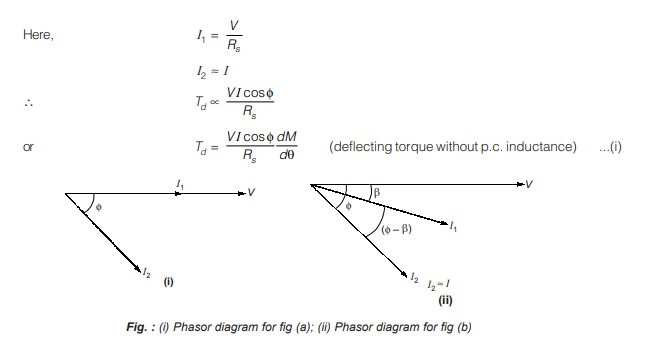
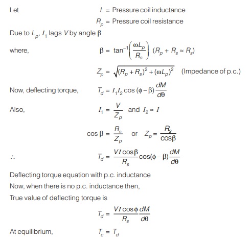
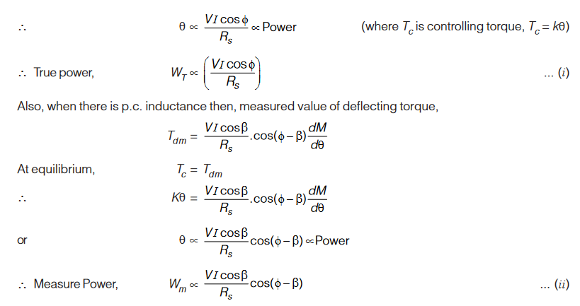
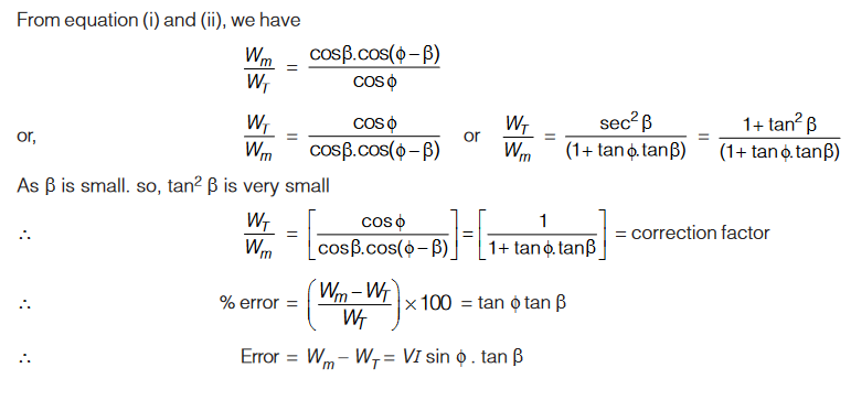
Wattmeter with Pressure Coil Inductance:
Two Wattmeter Method
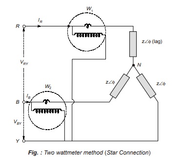
- In a 3-phase, 3-wire system we require 3 elements to measure power but since the common points of the pressure coil coincide with one of the lines, only two wattmeters or elements are required to measure the power.
- Above figure shows the connection diagram for measuring power in a 3-phase system using two-wattmeter method.
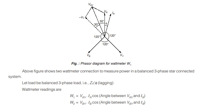
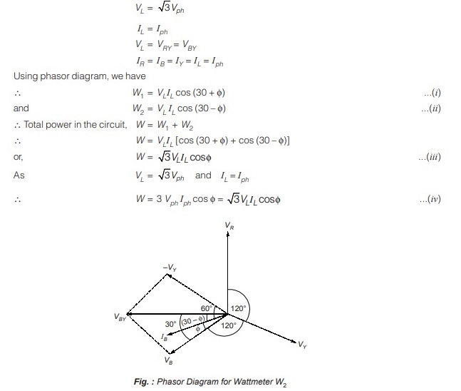
For star connection, we have
Measurement of Power Factor
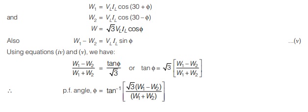
∴ p.f. of circuit = cos φ
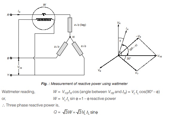
Measurement of Reactive Power using Wattmeter
For measurement of reactive power using wattmeter, the current coil is connected between one of the phases of R, Y, B (i.e., R) then, the potential coil should be connected between the remaining two phases (i.e., Y and B). Below figure shows the connection diagram for the measurement of 3 phase reactive power using wattmeter.
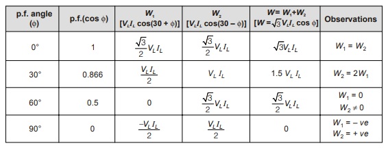
Variation in Wattmeter Readings
Remember:
- If one of the wattmeter shows –ve value then, this indicates that the load is a reactive. element, i.e., an inductor or a capacitor which consumes the reactive power.
- When p.f. angle = 60° or p.f. = 0.5, only single wattmeter measures entire 3-phase power.
- When p.f. angle = 60° or p.f. = 0.5, one wattmeter shows zero deflection.
- When p.f. angle > 60° or p.f. = 0.5, one of the wattmeter shows –ve deflection.
- When p.f. angle < 60° or p.f. = 0.5, two wattmeter shows +ve deflection.
- When one of the wattmeter shows –ve deflection, the range of p.f. is from 0 to 0.5.
- When two wattmeter show +ve deflection, then range of the p.f. is from 0.5 to 1.
<< Previous | Next >>
Must Read: What are the Electrical and Electronics Measurements?
Dear Aspirants,
Your preparation for GATE, ESE, PSUs, and AE/JE is now smarter than ever — thanks to the MADE EASY YouTube channel.
This is not just a channel, but a complete strategy for success, where you get toppers strategies, PYQ–GTQ discussions, current affairs updates, and important job-related information, all delivered by the country’s best teachers and industry experts.
If you also want to stay one step ahead in the race to success, subscribe to MADE EASY on YouTube and stay connected with us on social media.
MADE EASY — where preparation happens with confidence.
MADE EASY is a well-organized institute, complete in all aspects, and provides quality guidance for both written and personality tests. MADE EASY has produced top-ranked students in ESE, GATE, and various public sector exams. The publishing team regularly writes exam-related blogs based on conversations with the faculty, helping students prepare effectively for their exams.
