Electrical and Electronic Measurements: Types of Errors
Error: Deviation of the measured value from the true value of the quantity being measured is called an error.
A study of errors is a first step in finding ways to reduce them. Errors may arise from different sources and are classified as under:
- Gross error
- Systematic error
- Random error
| Gross Error | Systematic Error | Random Errors |
|---|---|---|
| 1. These types of error mainly comprises of human mistakes in reading instruments and recording and calculating measurement results. | 1. Systematic errors are classified into three types:
(i) Instrument Errors: • Occurs due to short coming in the instrument • Misuse of the instrument • Loading effect of the instrument (ii) Environmental Errors: • These errors occurs due to external environment factors like humidity, dust, vibrations or external magnetic field etc. (iii) Observation Errors: • Different experimenters may produce different results, when sound and light measurements are involved since no two observers possess the same physical response. |
1. Random errors are those errors whose causes can’t be established because of random variations in the parameters or the system of measurement. |
| 2. The experimenter is mainly responsible for these errors.
3. Some gross errors are easily detected while some are difficult to detect. 4. These errors can be avoided by taking great care in reading and recording the data. Also, two or three or even more readings should be taken for the quantity under measurement. |
2. The happenings or disturbances about which we are unaware are lumped together and called “Random” or “Residual” and error caused due to these happenings are called “Random” error. | |
| 5. Computational mistakes, incorrect adjustment and improper application of instruments can lead to gross errors. |
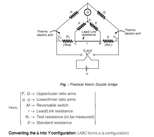
Measurement of Low Resistance using “Kelvin Double Bridge” Method
The Kelvin bridge is a modification of the wheat stone bridge and provides greatly increased accuracy in measurement of low value resistances.
The Kelvin double bridge incorporates the idea of a second set of ratio arms hence the name double bridge and the use of four terminal resistors for the low resistance arms.
Figure below shows schematic diagram of the Kelvin double bridge.
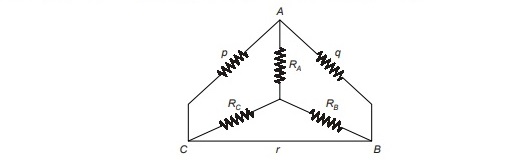
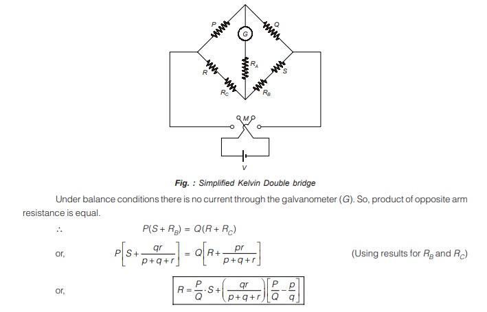
The bridge is simplified as shown below in figure.
<< Previous | Next >>
Must Read: What are the Electrical and Electronics Measurements?
Dear Aspirants,
Your preparation for GATE, ESE, PSUs, and AE/JE is now smarter than ever — thanks to the MADE EASY YouTube channel.
This is not just a channel, but a complete strategy for success, where you get toppers strategies, PYQ–GTQ discussions, current affairs updates, and important job-related information, all delivered by the country’s best teachers and industry experts.
If you also want to stay one step ahead in the race to success, subscribe to MADE EASY on YouTube and stay connected with us on social media.
MADE EASY — where preparation happens with confidence.
MADE EASY is a well-organized institute, complete in all aspects, and provides quality guidance for both written and personality tests. MADE EASY has produced top-ranked students in ESE, GATE, and various public sector exams. The publishing team regularly writes exam-related blogs based on conversations with the faculty, helping students prepare effectively for their exams.