Counters
A digital counter is a set of flip-flops whose states change in response to the pulses applied at the input to the counter.
As its name implies, a counter is used to count the pulses.
Counters can be classified into two types, based on the application of the clock pulse to the different flip-flops.
1. Asynchronous counter ⇒ Ripple counter, serial (or) series
2. Synchronous counter ⇒ Parallel counter
| Asynchronous Counter | Synchronous Counter |
|---|---|
|
All the flip-flops are not clocked simultaneously. |
All the flip-flops are clocked simultaneously. |
| Output of one flip-flop is used to generate clock for the another flip-flop. |
There is no connection between the output of one flip-flop and the clock of the another flip-flop. |
|
Only fixed sequence of states can be designed by using these counters. |
Any required sequence of states can be designed by using these counters. |
| Design and implementation is very simple even for more number of states (if they are in proper sequence). |
Design and implementation become tedious and complex as the number of states increases. |
|
Operation is slower as the clock must be propagated through all the flip-flops before reaching the last flip-flop. |
Operation is faster, as all the flip-flops get the clock simultaneously. |
| Decoding errors will occur. | No decoding errors will occur. |
| e.g. Ripple up counter, Ripple down counter | e.g. Ring counter, Johnson counter. |
Modulus of the Counter
- The total number of distinct states, that are indicated by a counter in the counting sequence is called the modulus of the counter. It is also called as “MOD or MOD-number”.
- For a counter having “n” number of flip-flops, MOD ≤ 2n.
- A counter which goes through all the possible states is called the “full modulus counter”.
- If an n-bit counter having MOD = 2n and the sequence of the states is either ascending or descending order then the counter can be called as a “Binary counter” also called as (2n : 1) scalar counter.
- A counter in which the maximum number of states can be changed is called the “variable modulus counter”.
- The final state of the counter sequence is called the terminal count.
- Sometimes the “modulo-M counter” also can be called as “divide-by-M counter”.
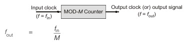
- So a counter can be used as a frequency divider circuit.
- The output clock of a counter is nothing but the signal present at the output of the flip-flop which is getting the input clock very lately in asynchronous counters. It serves as the clock signal to the next stage flip-flop in asynchronous counters. In synchronous counters, all the flip-flops have same clock and the output signal of the flip-flop is generally used to drive the input of next stage flip-flop.
- When two counters are cascaded with MOD-M followed by MOD-N, then the MOD of the resultant counter is “M × N” and the counter is called “MOD-MN” counter.
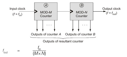
- Cascading of the counters is nothing but connecting the clock output of one counter as a clock input to the next following counter.
- Here, both A and B may be asynchronous (or) both may be synchronous (or) one may be synchronous and another may be asynchronous.
Applications of the Counters
1. To create time delays.
2. To generate a required sequence of bits.
3. To produce non sequential binary counts.
4. Used as frequency divider circuits.
5. To count the number of clock pulses (or) number of items in an industry.
6. To perform the timing function as in digital watches.
7. To calculate the pulse repetition rate.
8 For distance measurement in RADAR system.
9. Used in analog to digital conversion circuits.
<< Previous | Next >>
Must Read: What is Boolean algebra?
Dear Aspirants,
Your preparation for GATE, ESE, PSUs, and AE/JE is now smarter than ever — thanks to the MADE EASY YouTube channel.
This is not just a channel, but a complete strategy for success, where you get toppers strategies, PYQ–GTQ discussions, current affairs updates, and important job-related information, all delivered by the country’s best teachers and industry experts.
If you also want to stay one step ahead in the race to success, subscribe to MADE EASY on YouTube and stay connected with us on social media.
MADE EASY — where preparation happens with confidence.
MADE EASY is a well-organized institute, complete in all aspects, and provides quality guidance for both written and personality tests. MADE EASY has produced top-ranked students in ESE, GATE, and various public sector exams. The publishing team regularly writes exam-related blogs based on conversations with the faculty, helping students prepare effectively for their exams.
