Sources: Independent Voltage Sources & Independent Current Source
A source is a device which converts mechanical, chemical, thermal or some other form of energy into electrical energy. In other words, the source is an active network element meant for generating electrical energy.
Sources are classified as voltage sources and current sources. Further, it may be classified as dependent and independent sources.
Independent Voltage Sources
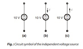
An independent voltage source is an idealized circuit component that fixes the voltage in a branch which is completely independent of the current through it. Thus, if we are given an independent voltage source and are notified that the terminal voltage is 10 V then we always assume this voltage, regardless of the current flowing.
Remember:
- The presence of the plus sign at the upper end of the symbol of the independent voltage source in figure does not necessarily mean that the upper terminal is numerically positive with respect to the lower terminal. Instead, it means that the upper terminal is Vs volts positive with respect to the lower.
- If at some instant Vs happens to be negative, then the upper terminal is actually negative with respect to the lower at that instant.
Independent Current Source
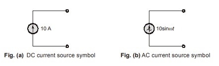
An independent current source is an idealized circuit component that pushes a constant flow of electrons through an electrical circuit regardless of the load presented to it. In other words, the current through the element is completely independent of the voltage across it.
The symbol for an independent DC current and an independent AC current source is shown in below figure.
Remember:
It is a common mistake to view an independent current source as having zero voltage across. its terminals while providing a fixed current. In fact, we do not know a priori what the voltage across a current source will be—it depends entirely on the circuit to which it is connected.
Note:
Generally, independent sources supply power to the circuit. However, they can be connected into a circuit in such a way that they absorb power from the circuit.
Dependent Source
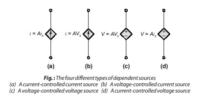
A dependent (or controlled) source is an active element in which the source quantity is controlled by another voltage or current. The control of the dependent source is achieved by a voltage or current of some other element in the circuit and the source can be voltage or current, it follows that there are four possible types of dependent sources, namely :
- A voltage-controlled voltage source : V = Avx
- A current-controlled voltage source : V = Aix
- A voltage-controlled current source : i = Avx
- A current-controlled current source : i = Aix
Note:
- A different symbol, in the shape of a diamond, is used to represent dependent sources.
- Dependent sources are very useful in describing certain types of electronic circuits.
- A dependent source may absorb or supply power.
Series Resistance and Voltage Division
Two elements are said to be in series provided they are connected by simple node hence current through them are same. 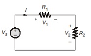
Voltage division is used to express the voltage across one of several series resistors in terms of the voltage across the combination. In above figure, the voltage across R2 is found via KVL and Ohm’s law:
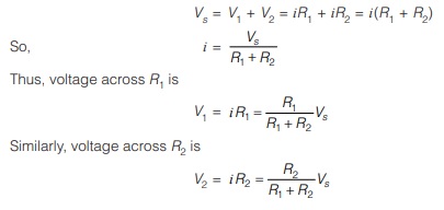
Remember:
In general, if a voltage divider has N resistors with values R1, R2, R3 … RN in series with the source voltage Vs , then voltage across the Kth resistor (RK) will be
VK = RK/R1+R2+…+RN.Vs
Parallel Resistance and Current Division
Two element are said to be in parallel if they are connected between same pair of node, hence voltage across them are same. 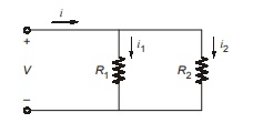
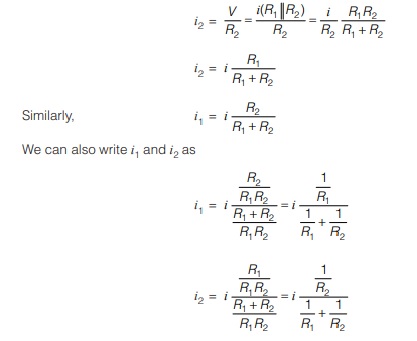
The dual of voltage division is current division. We are now given a total current supplied to several parallel resistors, as shown in the circuit.
The current flowing through R2 is
Remember:
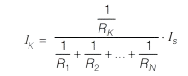
If N resistors with resistance R1, R2, R3 … RN are connected in parallel across a current source Is , then the current through the Kth resistor (RK) will be
Wye-Delta Transformations
We saw previously that identifying parallel and series combinations of resistors can often lead to a significant reduction in the complexity of a circuit. In situations where such combinations do not exist, we often make use of ∆-Y (Delta-wye) conversion. 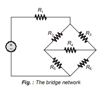
Consider the circuit in above figure. There are no series or parallel combinations that can be made to further simplify any of the circuits, without any sources present, no source transformations can be performed. However, it is possible to convert these two types of networks.
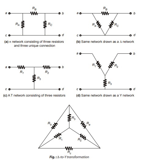
Above figure shows both the interconnection superimposed in the same circuit. The conversion formulas from wye to delta and delta to wye discussed as following.
Wye to Delta Conversion
To convert from Y-network to equivalent ∆-from, the new resistor values are calculated as
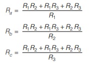
Each resistor in the ∆-network is the sum of all possible products of Y-resistors taken two at a time, divided by the opposite Y-resistor.
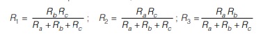
Delta to Wye Conversion
To convert ∆-interconnection into equivalent Y-from, the new resistor values are calculated as
The Supernode
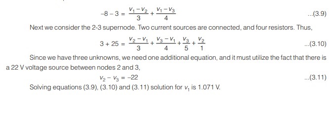
As an example of how voltage sources are best handled when performing nodal analysis, consider the circuit shown below in figure (a). We still assign the same node-to-reference voltages v1, v2 and v3. Previously, the next step was the application of KCL at each of the three non-reference nodes. If we try to do that once again, we see that we will run into some difficulty at both nodes 2 and 3, for we do not know what the current is in the branch with the voltage source. There is no way by which we can express the current as a function of the voltage, for the definition of a voltage source is exactly that the voltage is independent of the current.
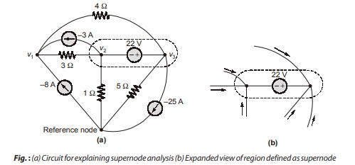
The easier method is to treat node 2, node 3 and the voltage source together as a sort of supernode and apply KCL to both nodes at the same time; the supernode is indicated by the region enclosed by the broken line in fig. (a). This is okay because if the total current leaving node 2 is zero and the total current leaving node 3 iszero, then the total current leaving the combination of the two nodes is zero. This concept is represented graphically in the expanded view in fig. (b).
The KCL equation at node 1 is
The supernode analysis of the circuit involves taking the following steps:
• Step-1 : Count the number of nodes (N).
• Step-2 : Designated a reference node. The number of terms in your nodal equations can be minimized by selecting the node with the greatest number of branches connected to it.
• Step-3 : Label the nodal voltages (there are N – 1 of them).
• Step-4 : If the circuit contains voltage sources, form a supernode about each one. This is done by enclosing the source, its two terminals and any other elements connected between the two terminals within a broken-line enclosure.
• Step-5 : Write a KCL equation for each of the non-reference node and for each supernode that does not contain the reference node. Sum the currents flowing into a node from sources on one side of the equation. On the other side, sum the currents flowing out of the node through resistors. Pay close attention to “–” signs.
• Step-6 : Relate the voltage across each voltage source to nodal voltages. This is accomplished by simple application of KVL; one such equation is needed for each supernode defined.
• Step-7 : Express any additional unknown such as currents or voltages other than nodal voltages in terms of appropriate nodal voltages. This situation can occur if voltage sources or dependent sources appear in our circuit.
• Step-8 : Organize the equations. Group terms according to nodal voltages.
• Step-9 : Solve the system of equations for the nodal voltages (there will be N – 1 for them).
Note:
- The voltage source inside the supernode provides a constraint equation needed to solve for the node voltages.
- A supernode has no voltage of its own.
- A supernode requires the application of both KCL and KVL.
<< Previous | Next >>
Must Read: What is Network Theory?
Dear Aspirants,
Your preparation for GATE, ESE, PSUs, and AE/JE is now smarter than ever — thanks to the MADE EASY YouTube channel.
This is not just a channel, but a complete strategy for success, where you get toppers strategies, PYQ–GTQ discussions, current affairs updates, and important job-related information, all delivered by the country’s best teachers and industry experts.
If you also want to stay one step ahead in the race to success, subscribe to MADE EASY on YouTube and stay connected with us on social media.
MADE EASY — where preparation happens with confidence.
MADE EASY is a well-organized institute, complete in all aspects, and provides quality guidance for both written and personality tests. MADE EASY has produced top-ranked students in ESE, GATE, and various public sector exams. The publishing team regularly writes exam-related blogs based on conversations with the faculty, helping students prepare effectively for their exams.
