Network Parameters
What is Network Parameters?
A pair of terminals through which a current may enter or leave a network is known as a port. Most of the circuits we have dealt with so far are two-terminal or one-port circuits, represented in fig. (a). We have considered the voltage across or current through a single pair of terminals-such as the two terminals of a resistor, a capacitor, or an inductor. We have also studied four-terminal or two-port circuit involving op-amps, transistors and transformer as shown in fig. (b). Thus, we can say that a two-port network is an electrical network with separate ports for input and output.
In general, a network may have n ports. In this chapter, we are mainly concerned with two-port networks (or simply, two ports).
In two port network four variables are use (i.e., V1, V2, I1, I2 ) out of four variable, we can chose two variable in six different way (4C2), and hence we have six sets of two-port.
- Z-parameters (Impedance parameters)
- Y-parameters (Admittance parameters)
- ABCD parameters (Transmission parameters)
- A’ B’ C’ D’ parameters (Inverse transmission parameters)
- h-parameters (Hybrid parameters)
- g-parameters (Inverse hybrid parameters)
Z-Parameters
The Z-parameter, or impedance parameters, relates current to voltage, as one would expect. The Z-parameters are 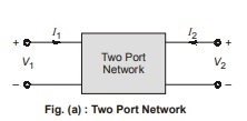 the inverse of the Y-parameters in most cases.
The terminal voltage can be related to the terminal currents as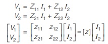
The values of the parameters can be evaluated by setting I1 = 0 (input port open-circuit) or I2 = 0. (output port open-circuited). Thus
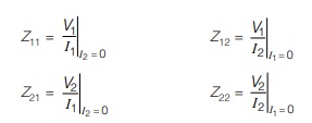
where,
Z11 = Open-circuit input impedance
Z12 = Open-circuit transfer impedance
Z21 = Open-circuit transfer impedance from port 2 to port 1
Z22 = Open-circuit output impedance
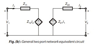
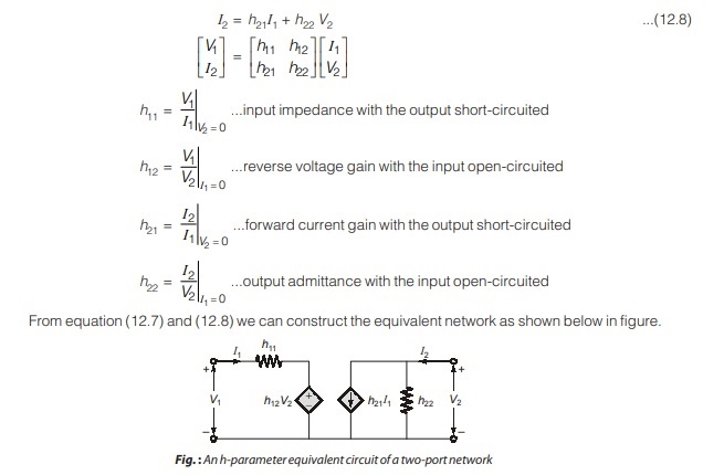
The equivalent circuit representation of equation (12.1) and (12.2) is in figure shown below, where Z12 I2 and Z21 I1 are current-controlled voltage sources (CCVS).
The equivalent circuit for equation (12.1) and (12.2) is given as
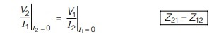
Condition of Reciprocity and Symmetry
Reciprocity network : A two port network is said to be reciprocal if the ratio of response to excitation remains the same even when there positions are interchanged.
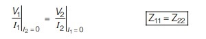
Symmetrical Network: Network is said to be symmetrical if the ratio of current and voltage at some (one) port is same as ratio of current and voltage at other port.
Note:
For small independent networks symmetry can be identified by the “mirror image property”.
Y-parameters
In the previous section we saw that impedance parameters may not exist for a two-port network. So, there is a need for an alternative means of describing such a network. This need may be met by the second set of parameter which we obtain by expressing the terminal currents in terms of the terminal voltages.
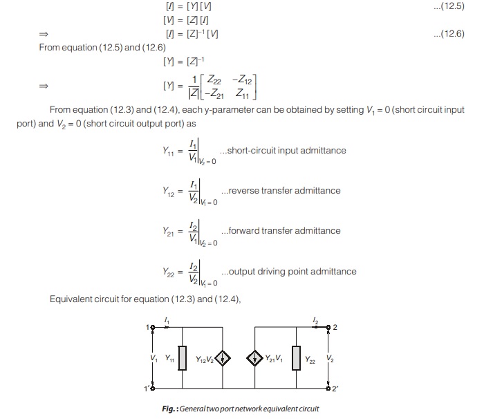
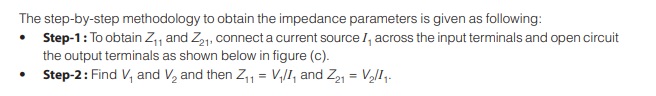
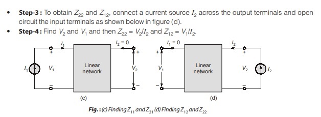
The step-by-step methodology to obtain the admittance parameters is given as following:
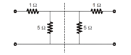
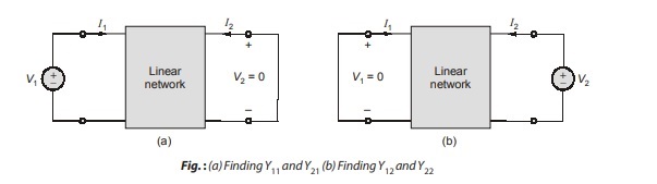
- Step-1 : To obtain Y11 and Y21, connect a voltage source V1 across the input terminals and short circuit the output terminals as shown below in fig. (a).
- Step-2 : Find I1 and I2 and then Y11 = I1/V1 and Y21 = I2/V1.
- Step-3 : To obtain Y22 and Y12, connect a voltage source V2 across the output terminals and short circuit the input terminals as shown below in fig. (b).
- Step-4 : Find I1 and I2 and then Y22 = I2/V2 and Y12 = I1/V2.
Condition of Reciprocity and Symmetry
For reciprocal network:
Y12 = Y21
For symmetrical network:
Y11 = Y22
Note:

h-parameters or Hybrid Parameters
The Z and Y parameters of two-port network do not always exist. So, there is a need for developing another set of parameters. This third set of parameters is based on making V1 and I2 the dependent variable. Thus, we obtain h parameter which is also known as the hybrid parameters.
The hybrid parameters (h-parameters) would find wide usage in electronic circuits, especially in constructing models for transistors.
The parameters of a transistor cannot be measured either by short-circuit admittance parameter measurement or open-circuit impedance parameter measurement alone, because of the forward bias of the base emitter junction, the device has a very low input resistance. For open-circuit impedance measurement of Z12 and Z22, it is very difficult to make the input open circuited. Z11 and Z21 can be measured by open-circuit impedance measurements, since the collector-emitter junction is reversed biased.
By making a short-circuit admittance parameter measurement, Y12 and Y22 can be measured by short circuiting the input port, but Y11 and Y21 cannot be measured since the collector-emitter junction is reverse biased.
Some kind of parameter representation is required by which some parameters are measured by open circuiting the input port, while the rest of the parameters can be measured by short-circuiting the output port. This is the so-called hybrid parameter representation. This parameter representation is a hybrid of short-circuit admittance and open-circuit impedance measurement.
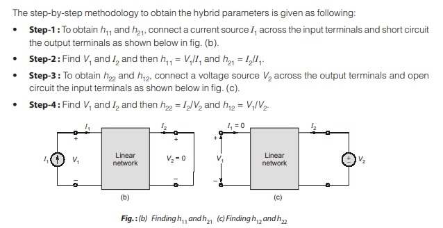
One set of equations result when the voltage of the input port and the current of the output port are expressed in terms of the current of the input port and the voltage of the output port [Refer Figure (a)], in the form
V1 = h11I1 + h12 V2
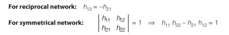
Condition of Reciprocity and Symmetry
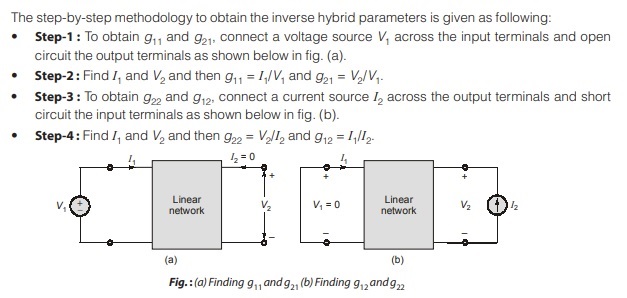
g-parameters or Inverse Hybrid Parameters
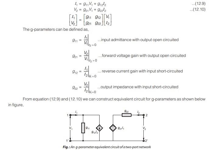
A set of parameters closely related to the h-parameters are the g-parameters or inverse hybrid parameter. These are used to describe the terminal currents and voltage as
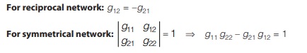
Condition of Reciprocity and Symmetry
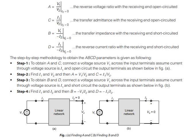
Transmission Parameters (ABCD)
Since, there are no restrictions on which terminal voltage and current should be considered independent and which should be dependent variables, we expect to be able to generate many set of parameters. Another set of parameter relates the variable at the input port to those at the output port.
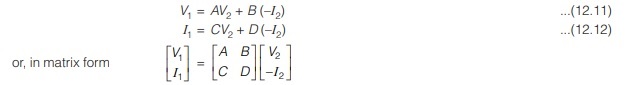
Equations (12.11) and (12.12) relate the input variables (V1 and I1) to the output variables (V2 and –I2). Notice that in computing the transmission parameter, –I2 is used rather than I2, because the current is considered to be leaving the network, as shown in below figure.
The transmission parameters are
Condition of Reciprocity and Symmetry

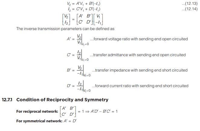
Inverse Transmission Parameters
Our last set of parameters may be defined by expressing the variables at the output port in terms of the variables at the input port we obtain
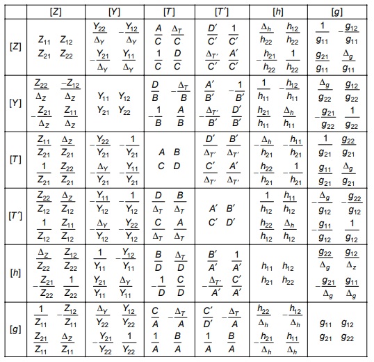
Inter Relations in Network Parameters
Dear Aspirants,
Your preparation for GATE, ESE, PSUs, and AE/JE is now smarter than ever — thanks to the MADE EASY YouTube channel.
This is not just a channel, but a complete strategy for success, where you get toppers strategies, PYQ–GTQ discussions, current affairs updates, and important job-related information, all delivered by the country’s best teachers and industry experts.
If you also want to stay one step ahead in the race to success, subscribe to MADE EASY on YouTube and stay connected with us on social media.
MADE EASY — where preparation happens with confidence.
MADE EASY is a well-organized institute, complete in all aspects, and provides quality guidance for both written and personality tests. MADE EASY has produced top-ranked students in ESE, GATE, and various public sector exams. The publishing team regularly writes exam-related blogs based on conversations with the faculty, helping students prepare effectively for their exams.
