Difference between Performance of Open Loop and Closed Control Systems
| Open Loop Control System | Closed Loop Control System |
|---|---|
| 1. Open loop system is not accurate because behaviour of the system does not change if its output changes. | 1. Closed loop system is accurate because behaviour of the system does change if its output changes. |
| 2. It either has no sense or it has partial sense but not complete sense. | 2. It has complete sense. |
| 3. Time constant of the open loop control system is larger due to which transients takes large time to die out hence open loop system is slow. | 3. Time constant of the closed loop control system is smaller due to which transient dies out rapidly. Hence, closed loop control system is fast. |
| 4. Effect of external disturbance and internal parameter variations is more in open loop system, i.e., open loop is more sensitive. | 4. Effect of external disturbance and internal parameter variations is less in closed loop system, i.e., closed loop system is less sensitive. |
| 5. Open loop system are simple and economical. | 5. Closed loop system is complex and expensive. |
| 6. Open loop system is stable, can become unstable but cannot be stabilized. | 6. Closed loop system is stable, can become unstable but can be stabilized. |
Transfer Function and Impulse Response Function
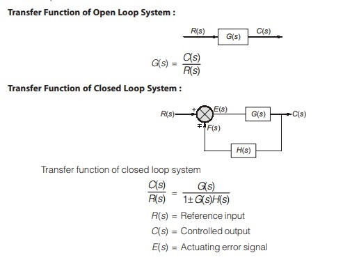
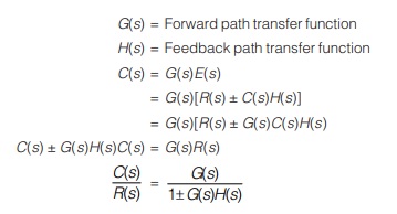
In control theory, transfer functions are commonly used to characterise the input-output relationships of components or systems that can be described by linear, time-invariant differential equations. Transfer Function
The transfer function of a linear, time-invariant, differential equation system is defined as the ratio of the Laplace transform of the output (response function) to the Laplace transform of the input (driving function) under the assumption that all initial conditions are zero.
Properties of Transfer Function
The properties of the transfer function are summarized as follows:
- The transfer function is defined only for a linear time-invariant system. It is not defined for non-linear or time variant systems.
- The transfer function between an input variable and an output variable of a system is defined as the Laplace transform of the impulse response. Alternately, the transfer function between a pair of input and output variables is the ratio of the Laplace transform of the output to the Laplace transform of the input.
- All initial conditions of the system are set to zero.
- Transfer function is independent of the input of the system.
- The transfer function of a continuous-data system is expressed only as a function of the complex variables. It is not a function of the real variable, time, or any other variable that is used as the independent variable or discrete-data system modelled by difference equations, the transfer function is a function of Z, when the Z-transform is used.
- If the system transfer function has no poles or zeros with positive real parts, the system is a minimum phase system.
Non-minimum phase functions are the functions which have poles or zeros on right hand side of s-plane. - The stability of a time-invariant linear system can be determined from its characteristic equation.
Characteristic equation: The characteristic equation of a linear system is defined as the equation obtained by setting the denominator polynomial of the closed loop transfer function to zero.
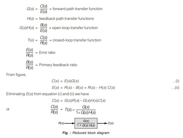
Block Diagram of a Closed-loop System
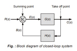
Figure shows the block diagram of a negative feedback system. With reference to this figure, the terminology used in block diagrams of control systems is given below.
R(s) = reference input signal
C(s) = output signal or controlled variable
B(s) = feedback signal
E(s) = actuating signal or error signal
<< Previous | Next >>
Must Read: What is a Control System?
Dear Aspirants,
Your preparation for GATE, ESE, PSUs, and AE/JE is now smarter than ever — thanks to the MADE EASY YouTube channel.
This is not just a channel, but a complete strategy for success, where you get toppers strategies, PYQ–GTQ discussions, current affairs updates, and important job-related information, all delivered by the country’s best teachers and industry experts.
If you also want to stay one step ahead in the race to success, subscribe to MADE EASY on YouTube and stay connected with us on social media.
MADE EASY — where preparation happens with confidence.
MADE EASY is a well-organized institute, complete in all aspects, and provides quality guidance for both written and personality tests. MADE EASY has produced top-ranked students in ESE, GATE, and various public sector exams. The publishing team regularly writes exam-related blogs based on conversations with the faculty, helping students prepare effectively for their exams.