Pulse Modulation
The modulation technique in which transmitted signal is in the form of digital pulses is called digital modulation system. Normally, the signals produced from various sources is analog in nature. e.g. audio signal captured in microphone, video signal (infinite possibilities of colour at single point and hence is continuous) all are analog signals. These can be converted into digital form using ADC (Analog to Digital converters) because there are certain advantages of digital transmission over analog transmission.
Analog Communication Versus Digital Communication
|
Analog Communication |
Digital Communication |
| Transmitted modulated signal is analog in nature. | Transmitted signal is digital i.e. train of digital pulses. |
| Amplitude, frequency or phase variations in the transmitted signal represent the information or message. | Amplitude, width or position of the transmitted pulses is constant. The message is transmitted in the form of code words. |
| Noise immunity is poor for AM, but improved for FM and PM. | Noise immunity is excellent. |
| It is not possible to separate out noise and signal. Therefore, repeaters cannot be used. | It is possible, to separate signal from noise. Therefore, repeaters can be used. |
| Coding is not possible. | Coding techniques can be used to detect and correct the errors. |
| Bandwidth required is lower than that for the digital modulation method. | Due to higher bit rates, higher channel bandwidth is required. |
| FDM is used for multiplexing. | TDM is used for multiplexing. |
| Non suitable for transmission of secret information in military applicants. | Due to coding techniques, it is suitable for military applications. |
| Analog modulation systems are AM, FM, PM, PAM, AWM, etc. | Digital modulation systems are PCM, DM, ADM, DPCM etc. |
Applications of Digital Communication
- Long distance communication between earth and spaceships.
- Satellite communication.
- Military communication which needs coding.
- Data and computer communications.
In continuous wave modulation studied earlier, some parameter of a sinusoidal carrier wave is varied continuously in accordance with message signal. Similarly, in pulse modulation, which we are going to study in this chapter, some parameter of a pulse train is varied in accordance with the message signal.
Pulse modulation can be classified in two families:
Analog Pulse Modulation:
In this, a periodic pulse train is used as the carrier wave. Some characteristic of each pulse (e.g. amplitude, duration or position) is varied in a continuous manner in accordance with corresponding sample value of message signal. Here, information is transmitted in analog form but transmission occurs at discrete times.
Digital Pulse Modulation:
Here, message signal is transmitted in the form that is discrete in both domains-amplitude as well as time. For conversion of any analog signal into digital domain, two operations are necessary, namely, sampling and quantization.
Differential Pulse Code Modulation
PCM is not a very efficient system because it generates so many bits and requires so much bandwidth to transmit. Many different ideas have been proposed to improve the encoding efficiency of A/D conversion. In general, these ideas exploit the characteristics of the source signals. DPCM is one such scheme.
In analog message was can make a good guess about sample value from knowledge of past sample values. In other words, the sample values are not independent, and generally there is a great deal of redundancy in the Nyquist samples.
- As the most message signals have high correlation (similarity) among them, so it is possible to classify the information present in them into predictable and unpredictable parts.
- DPCM first estimates the predictable part from the signal and then codes the error signal in terms of unique binary words as in PCM.
- Due to the less variance among the unpredictable part of the signal, as compared to original signal, binary words of smaller length are used for coding this unpredictable part.
Delta Modulation
As we have observed that transmission channel bandwidth is quite large in PCM, hence to overcome this problem, delta modulation is used.
Delta modulation is obtained by simplifying the quantization and encoding process of PCM. Here, sampling rate is much higher than nyquist rate. This over sampling will result in samples which are very close and hence high correlation among them. Under this condition, it is assumed that two successive samples will differ only by δ i.e. if current sample is larger than previous sample, then it is quantized by +δ and if it smaller, then it is quantized by –δ. Hence, it can be coded by using 1-bit only.
⇒ 1 represent +δ ; 0 represent –δ.
It demands for minimum possible channel bandwidth requirements.
BW = nfs/2
Here, n = 1 BW = fs/2
Advantages of DM
- Since only 1-bit per sample is transmitted, therefore channel bandwidth requirement for transmission is very less.
- Transmitter and receiver implementation is very easy.
Drawbacks of DM
There are two main drawbacks of DM:
- Slope overload distortion.
- Granular or idle noise.
Adaptive Delta Modulation (ADM)
As we have seen that delta modulation fails to track the very slow or very fast varying message signals. So, in ADM, the step size is made adaptive to the variations of the message signal m(t). If input is varying fast, the step size is increased. If input is varying slowly, the step size is decreased. Hence ADM can take continuous changes in step size.
Adaptive Delta Modulation Transmitter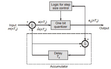
- The logic for step size control is added here. The step size varies in accordance with the one bit quantizer output.
- For instance, if one bit quantizer output is high, then step size may be doubled for next sample and if one bit quantizer output is low, then step size may be reduced.
Advantages of ADM
- (S/N) ratio improve because of the reduction in slope overload distortion and granular noise.
- Because of variable step size, dynamic input range of ADM is more than DM.
- Better utilization of bandwidth.
<< Previous | Next >>
Must Read: What is Communication?
Dear Aspirants,
Your preparation for GATE, ESE, PSUs, and AE/JE is now smarter than ever — thanks to the MADE EASY YouTube channel.
This is not just a channel, but a complete strategy for success, where you get toppers strategies, PYQ–GTQ discussions, current affairs updates, and important job-related information, all delivered by the country’s best teachers and industry experts.
If you also want to stay one step ahead in the race to success, subscribe to MADE EASY on YouTube and stay connected with us on social media.
MADE EASY — where preparation happens with confidence.
MADE EASY is a well-organized institute, complete in all aspects, and provides quality guidance for both written and personality tests. MADE EASY has produced top-ranked students in ESE, GATE, and various public sector exams. The publishing team regularly writes exam-related blogs based on conversations with the faculty, helping students prepare effectively for their exams.
