Amplitude Modulation
In analog communication, message is analog and the carrier is sine wave, which is also analog in nature. The modulation techniques in analog communication can be classified into amplitude modulation (AM) and angle modulation techniques. The amplitude of the carrier signal is varied in accordance with the message to obtain modulated signal in case of amplitude modulation.
After studying the theory of amplitude modulation techniques, one will be able to know that an AM wave is made of a number of frequency components having a specific relation to one another. Based on this observation, AM can be further classified as double sideband full carrier (DSBFC), double sideband suppressed carrier (DSBSC), single sideband (SSB) and vestigial sideband (VSB) modulation techniques. This is based on how many components of the basic amplitude modulated signal are chosen for transmission. This is followed by a description of different methods for the generation of AM, DSBSC, SSB and VSB signals. To summarize, this chapter describes the basic essence of all the amplitude modulation techniques. In this chapter AM and its variants, their differences, merits and demerits are discussed. The students will also be able to calculate the frequencies present, plot the spectrum, the power or current associated with different frequency components and finally bandwidth requirements.
Amplitude modulation is the process of changing the amplitude of a relatively high frequency carrier signal in proportion with the instantaneous value of the modulating signal (information).
Amplitude modulation is a relatively inexpensive, low quality form of modulation that is used for commercial broadcasting of both audio and video signals.
Consider a sinusoidal carrier wave c(t) defined by
c(t) = Ac cos(2πfct)
where the peak value Ac , is called the carrier amplitude and fc is called the carrier frequency. For convenience, we have assumed that the phase of the carrier wave is zero. It is justified in making this assumption since the carrier source is always independent of the message source. We refer to m(t) as the message signal which is baseband in nature. Amplitude modulation is defined as a process in which the amplitude of the carrier wave c(t) is varied linearly with the message signal ) is varied linearly with the message signal m(t) keeping other parameters constant.
Amplitude modulation is linear process but AM modulators are non-linear devices.
Time-Domain Description
The standard form of an amplitude-modulated (AM) wave is defined by
s(t) = Ac[1 + ka m(t)] cos(2πfct)
where ka is a constant called the amplitude sensitivity of the modulator. The modulated wave so defined is said to be a “standard” AM wave, because its frequency content is fully representative of amplitude modulation.
The amplitude of the time function multiplying cos(2πfct) is called the envelope of the AM wave s(t). Using a(t) to denote this envelope, we may thus write
a(t) = Ac|1 + kam(t)|
Two cases of particular interest arise, depending on the magnitude of kam(t), compared to unity.
For case 1, we have
|kam(t)| ≤ 1, for all t
Under this condition, the term 1 + kam(t) is always nonnegative. We may therefore simplify the expression for the envelope of the AM wave by writing
a(t) = Ac[1 + kam(t)],
For case 2, on the other hand, we have
kam(t)> 1, for all t
Under this condition, we must use equation (i) for evaluating the envelope of AM wave.
The maximum absolute value of The maximum absolute value of kam(t) multiplied by 100 is referred to as the percentage modulation.
Note:
The envelope of the AM wave has a waveform that bears a one-to-one correspondence with that of the message signal if and only if the percentage modulation is less than or equal to 100%. This correspondence is destroyed if the percentage modulation exceeds 100%. In the later case, the modulated wave is said to suffer from envelope distortion, envelope distortion and the wave is said to be over modulated.
The complexity of the detector (i.e. the demodulation circuit used to recover the message signal from the incoming AM wave at the receiver) is greatly simplified if the transmitter is designed to produce an envelope a(t) that has the same shape as the message signal m(t).For this, two conditions are need to be satisfied.
- The percentage modulation should be less than 100%, so as to avoid envelope distortion.
- The message bandwidth, fm, should be small as compared to the carrier frequency fc, so that the envelope a(t) may be visualized satisfactorily. Here, it is assumed that the spectral content of the message signal is negligible for frequencies outside the interval –fm≤ f ≤ fm i.e., message signal is basedband in nature.
Observations
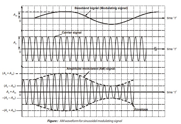
- The frequency of the sinusoidal carrier is much higher than that of the modulating signal.
- In AM, the instantaneous amplitude of the sinusoidal high frequency carrier is changed in proportion to the instantaneous amplitude of the modulating signal. This is the principle of AM.
- The time domain display of AM signal is as shown in figure. This AM signal is transmitted by a transmitter. The information in the AM signal is contained in the amplitude variations of the carrier of the envelope shown by dotted lines .
- Note that the frequency and phase of the carrier remain constant.
- AM is used in the applications such as radio transmission, TV transmission.
<< Previous | Next >>
Must Read: What is Communication?
Dear Aspirants,
Your preparation for GATE, ESE, PSUs, and AE/JE is now smarter than ever — thanks to the MADE EASY YouTube channel.
This is not just a channel, but a complete strategy for success, where you get toppers strategies, PYQ–GTQ discussions, current affairs updates, and important job-related information, all delivered by the country’s best teachers and industry experts.
If you also want to stay one step ahead in the race to success, subscribe to MADE EASY on YouTube and stay connected with us on social media.
MADE EASY — where preparation happens with confidence.
MADE EASY is a well-organized institute, complete in all aspects, and provides quality guidance for both written and personality tests. MADE EASY has produced top-ranked students in ESE, GATE, and various public sector exams. The publishing team regularly writes exam-related blogs based on conversations with the faculty, helping students prepare effectively for their exams.
