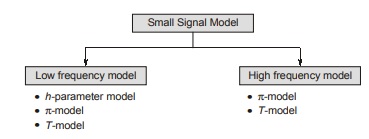
Small Signal Model of BJT
It is the equivalent circuit of BJT and it is used in analysis of small signal model of BJT amplifiers.
Transistor Hybrid Model
The basic assumption in arriving at transistor linear model or equivalent circuit is that the variations about quiescent point are assumed small, so that the transistor parameters can be considered constant over signal excursion. The operating (quiescent) values of current and voltage are determined by method employed to bias the transistor. These values do not enter into an incremental model, which is used only to find small-signal variations about the Q-point.
The transistor model presented here is given in terms of h-parameters, which are real numbers at audio frequencies, are easy to measure, can also be obtained from the transistor static characteristic curves, and are particularly convenient to use in circuit analysis and design. Furthermore, a set of h-parameters is specified for many transistors by the manufacturers.
The h-parameter model of BJT is defined by following equations for the circuit shown in figure below.
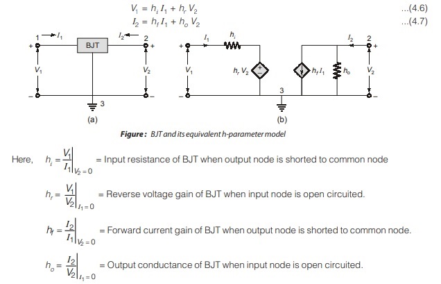
Typical h-Parameters Values for a Transistor (at IE ~1.3 mA)
| Parameter | CE | CC | CB |
|---|---|---|---|
|
h11 = hi |
1,100 Ω | 1,100 Ω | 21.6 Ω |
|
h12 = hr |
2.5 × 10⁻⁴ | ~1 | 2.9 × 10⁻⁴ |
|
h21 = hf |
50 | –51 |
–0.98 |
| h22 = ho | 24 µA/V | 25 µA/V |
0.49 µA/V |
| 1/ho | 40 k | 40 k |
2.04 Mho |
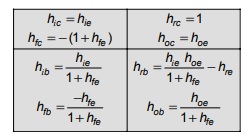
Approximate Conversion Formulas for Hybrid Parameters
Darlington Pair Configuration (CC – CC)
In some applications, it would be desirable to have a bipolar transistor with much larger current gain. Figure (a) shows a multi-transistor configuration, called Darlington pair Darlington pair or Darlington configuration, that provides increased current gain.
It is a cascade of two common collector amplifier.
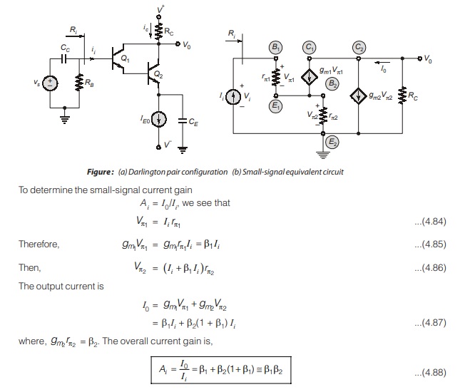
From equation (4.88), we see that overall small-signal current gain of Darlington pair is essentially the product of individual current gains.
Also the input resistance is approximately given by
Ri = 2β1rπ2
Advantages of Darlington Amplifier
- Very high input impedance.
- Unity voltage gain.
- Low output resistance.
- Very high current gain.
- It is used as voltage buffer.
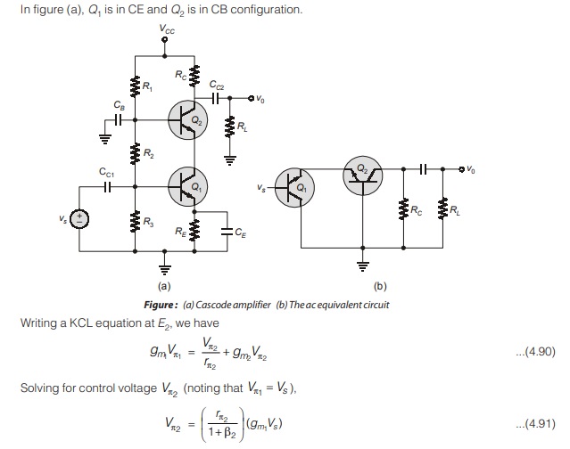
Cascode Configuration (CE – CB)
A slightly different multistage configuration, called cascode configuration, is shown in figure (a). The input is given to a common-emitter amplifier (Q1), which drives a common-base amplifier (Q2).
It is cascade of It is cascade of CE and CB amplifier amplifier.
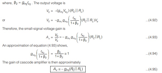
which is same as it is for single-stage common-emitter amplifier. This result is expected since the current gain of common-base circuit is essentially unity.
Advantages of Cascode Amplifier
- Current gain and voltage gain of cascode amplifier are same as single stage CE amplifier. But a cascode amplifier has large bandwidth in comparison to CE amplifier and hence it is usee as video frequency amplifier.
- In cascade amplifier, Miller effect is negligible i.e. increase in input capacitance is negligible which results in large bandwidth.
<< Previous | Next >>
Must Read: What are Analog Circuits?
Dear Aspirants,
Your preparation for GATE, ESE, PSUs, and AE/JE is now smarter than ever — thanks to the MADE EASY YouTube channel.
This is not just a channel, but a complete strategy for success, where you get toppers strategies, PYQ–GTQ discussions, current affairs updates, and important job-related information, all delivered by the country’s best teachers and industry experts.
If you also want to stay one step ahead in the race to success, subscribe to MADE EASY on YouTube and stay connected with us on social media.
MADE EASY — where preparation happens with confidence.
MADE EASY is a well-organized institute, complete in all aspects, and provides quality guidance for both written and personality tests. MADE EASY has produced top-ranked students in ESE, GATE, and various public sector exams. The publishing team regularly writes exam-related blogs based on conversations with the faculty, helping students prepare effectively for their exams.

