TRAVERSING METHODS
Traversing methods are classified as the basis of the instrument used for measuring the angle at the traverse station. Thus according to the type of instrument used, traversing methods can be classified as:
- Chain Traverse: In chain traverse, the directions of the traverse lines are fixed by taking adequate ties near the traverse stations. Chain traverse is not a precise method of traversing.
- Compass Traverse: Here in this method of traversing, the angles are measured with the help of a magnetic compass. But magnetic compass itself has its own limitations and thus accuracy of compass traverse is also very limited.
- Plane Table Traverse: It is a unique method of traversing in a way that traverse can be plotted directly in the field but it is not a very precise method.
- Stadia Traverse: In stadia traverse, the length of the traverse lines, the angles between the traverse lines and the elevations of the traverse stations are determined with the help of an instrument called tacheometer. This method gives elevations of traverse stations also in addition to provide horizontal control.
- Theodolite Traverse: In this method of traversing, the angles are measured with the help of a theodolite. It is the most precise method of traversing in order to have an accurate horizontal control.
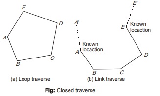
Closed Traverse
- This type of traverse initiates from one traverse station terminates either at the same starting station or at some other traverse station whose location is already known.
- As shown in figure (a), the traverse starts from the station ‘A’ and close on the same station to form a polygon. This is known as loop traverse.
- In link traverse as shown in figure, the location of traverse stations A and E are known with respect to reference stations A’ and E’ respectively.
- Any error in closed traverse can easily be detected and thus can easily be adjusted.
Open Traverse
- An open traverse initiates from one station whose location is known but terminates at a station whose location is neither known nor established.
- Open traverse is generally used for aligning a railway line or a highway or canal etc. An open traverse cannot be properly checked and adjusted.
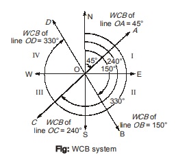
Whole Circle Bearing System
- In this system, the bearing of the line is measured from the north in clockwise direction.
- Thus whole circle bearing (abbreviated as WCB) of a line is the horizontal angle which the line makes with the north end of the reference meridian.
- The WCB of a line can vary from 0° to 360°.
- In the figure, the whole circle bearings of line OA, OB, OC and OD are 45°, 150°, 240° and 330° respectively.
Quadrantal Bearing System
- The quadrantal bearing of a line (abbreviated as QB) is the acute angle which the line makes with the meridian.
- Quadrantal bearing is measured either from north end or south end as the case may be i.e. whichever is nearer to the line. The quadrantal bearing of a line can vary from 0° to 90°.
- Letters N, E, W and S are used respectively for north, east, west and south.
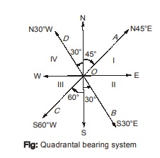
While writing the quadrantal bearing, the following steps are followed:
Step-1: First write either N or S if the line is nearer to the north or south, as the case may be.
Step-2: Write the angle (usually in degrees) which the line makes with the north or south, as the case may be.
Step-3: Write letter E if line is in either I or II quadrant or W if line is in either III or IV quadrant.
The whole circle bearing can be converted to quadrantal bearing and vice-versa.
| Conversion table for WCB and QB | |||
|---|---|---|---|
| Line | Quadrant | WCB | QB |
|
OA OB OC |
I II III |
0 = 0° to 90° 0 = 90° to 180° 0 = 180° to 270° |
NqE S(180° – q)E S(0 – 180°)W |
| OD |
IV |
q = 270° to 360° |
N(360° – 0)W |
<< Previous | Next >>
Must Read: What is Surveying?
Dear Aspirants,
Your preparation for GATE, ESE, PSUs, and AE/JE is now smarter than ever — thanks to the MADE EASY YouTube channel.
This is not just a channel, but a complete strategy for success, where you get toppers strategies, PYQ–GTQ discussions, current affairs updates, and important job-related information, all delivered by the country’s best teachers and industry experts.
If you also want to stay one step ahead in the race to success, subscribe to MADE EASY on YouTube and stay connected with us on social media.
MADE EASY — where preparation happens with confidence.
MADE EASY is a well-organized institute, complete in all aspects, and provides quality guidance for both written and personality tests. MADE EASY has produced top-ranked students in ESE, GATE, and various public sector exams. The publishing team regularly writes exam-related blogs based on conversations with the faculty, helping students prepare effectively for their exams.
