Prismatic Compass and Surveyor Compass
- The prismatic compass is a magnetic compass in which there is a prism for taking observations.
- It is smaller in size as compared to surveyor’s compass.
- It consist of a circular bar, about 85 to 100 mm diameter.
- Broad magnetic needle is used in prismatic compass.
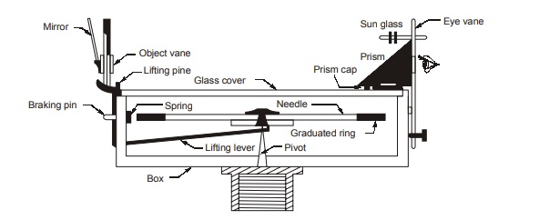
- The prismatic compass is used to measure the whole circle bearing (WCB) of a line, say line AB. The compass is set up at station A and temporary adjustments are done. Then turn the compass box till the ranging rod at station B gets bisected by the vertical hair in the vane when looked through the slit in the eye vane. Take reading of the aluminium ring through the aperture in the prism mounting. Read the graduation where the vertical hair of the object vane when produced appears to cut the image of the graduated ring.
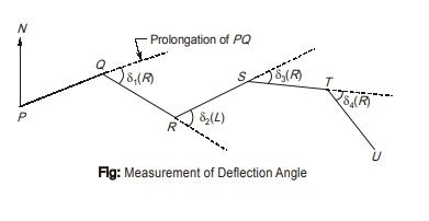
Measurement of Deflection Angles
- A deflection angle is the angle which the line makes with the prolongation of the preceding line.
- This deflection angle is designated as right (R ) when the deflection angle is measured clockwise and is designated as left (L) when the deflection angle is measured anticlockwise.
- The value of deflection angle can vary from 0° to 180°.
The following steps may be adopted to determine the right deflection angle ‘d’ at point Q as shown in Figure.
Step 1. Set up the Vernier theodolite at station Q and center it and level it. Keep the orientation of the vertical scale as face left. Set the Vernier A to zero and clamp the upper plate.
Step 2. Take back sight at station preceding station P and clamp the lower plate. Bisect P using the lower tangent screw.
Step 3. Plunge the telescope so the line of sight is now along the prolongation of the line PQ with reading on the Vernier still equal to zero.
Step 4. Unclamp the upper plate and turn the telescope clockwise to sight at station R. Bisect R using the upper tangent screw. Read both the verniers A and B. The mean of the two Vernier readings is the deflection angle, d
Step 5. Unclamp the lower plate and turn the telescope to sight at station P again. Telescope is in inverted position at this stage.
Step 6. Plunge the telescope so that the telescope is now in the normal position.
Step 7. Unclamp the upper plate and again sight at station R by turning the telescope clockwise. Clamp the upper plate and bisect R using the upper tangent screw. Read both the verniers A and B. In the above process, the deflection angle is doubled and thus one half of the total value is the deflection angle.
<< Previous | Next >>
Must Read: What is Surveying?
Dear Aspirants,
Your preparation for GATE, ESE, PSUs, and AE/JE is now smarter than ever — thanks to the MADE EASY YouTube channel.
This is not just a channel, but a complete strategy for success, where you get toppers strategies, PYQ–GTQ discussions, current affairs updates, and important job-related information, all delivered by the country’s best teachers and industry experts.
If you also want to stay one step ahead in the race to success, subscribe to MADE EASY on YouTube and stay connected with us on social media.
MADE EASY — where preparation happens with confidence.
MADE EASY is a well-organized institute, complete in all aspects, and provides quality guidance for both written and personality tests. MADE EASY has produced top-ranked students in ESE, GATE, and various public sector exams. The publishing team regularly writes exam-related blogs based on conversations with the faculty, helping students prepare effectively for their exams.
