What is Stress in Strength of Materials?
The fundamental concept of stress can be understood by considering a prismatic bar that is loaded by axial force P at the ends as shown. 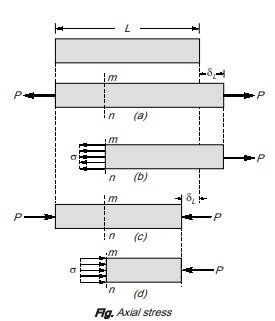
A prismatic bar is a straight structural member having constant cross-sectional area throughout its length. In the figure (a), axial force is acting away from the cross-section producing a uniform stretching of the bar, hence the bar is said to be in tension. Similarly in figure (c), axial force is acting towards the cross-section producing uniform compression of the bar, hence the bar is said to be in compression. To investigate the internal stresses produced
in the bar by axial forces, we make an imaginary cut at section mn as shown in figure (b) and (d). This section is taken perpendicular to the longitudinal axis of bar. Hence it is known as cross-section.
Now isolating the part of the bar to the right of the cut and considering the right of the cut as a free body. The force P has a tendency to move free body in the direction of load, so to restrict the motion of bar an internal force is induced which is uniformly distributed over cross-sectional area. The intensity of force developed, that is, internal force per unit area is called the stress. 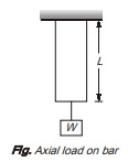
Stress differs from pressure because pressure is defined as the externally applied force on unit area while stress is internal resistive force on unit area. To have better understanding of difference between externally applied force and internal resistance. Consider a bar suspended from a fixed end and a weight W is gradually applied at its free end as shown in figure.
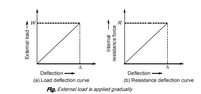
Case-I: Weight, W is applied gradually
Gradual loading means that value of load is zero at the starting time and gradually increases to value of W. Here, the bar gradually elongates with the increasing value of load. With increase in elongation, resistance forces say R will also increase gradually.
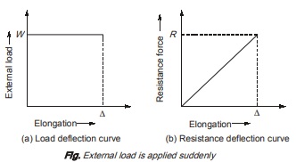
Case-II: Weight, W is applied suddenly
Here, external load variation with elongation of bar is such as that its value instantly increases to W. This sudden load will result into elongation of bar say ∆. When external load is applied suddenly, resistance force will be set up in bar, but unlike external load which is sudden, resistance force has always linear variation with elongation of bar.
Now, as clear from figure (a) and (b), intensity of pressure is not equal to stress induced in bar. Thus, stress can be defined as – “Stress is the internal resistance of a material offered against “Stress is the internal resistance of a material offered against deformation which is expressed in terms of force per unit area”.
Stress induced in material depends upon the nature of force, point of application and cross-sectional area of material. Stress can be tensile or tensile compressive in essive nature depending on the nature of load. Generally,
stress is represented by the Greek letter σ. We can calculate stress mathematically as σ = P/A
STRAIN 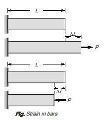
An axially loaded bar undergoes a change in length, becoming longer when in tension and shorter when in compression. The elongation or shortening in axially loaded member per unit length is known as strain. Strain is represented by ∈.
Mathematically, strain can be calculated as ∈ = ∆L/L
Strain is dimensionless quantity and is always expressed in the form of number. If the member is in tension then the strain is called tensile strain. If the member is in compression, then the strain is called compressive strain.
On the basis of length of member used in calculation of strain, strain can be of following two types:
(a) Engineering or Nominal Strain: Engineering or nominal strain is strain calculated, when length of member is taken as original length
Mathematically, ∈0 = ∆l/L0 where, l0 = original length of member
(b) True or Actual Strain : True or actual or Actual Strain is strain calculated, when length of member is taken as
actual length of member at loading
Mathematically ∈a = ∆l/la where, la = actual length of member
la = lo ± ∆l ‘+’ sign for tension; ‘–’ sign for compression
Stress Strain Curve for Tension
- A is limit of proportionality: Beyond this linear variation ceases. Hooke’s law is valid in OA.
- B is elastic limit: The maximum stress upto which a specimen regains its original length on removal of applied load. For mild steel, B is very near to A. However, for other materials B may be greater than A.
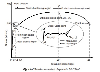
C′ is upper yield point: The magnitude of the stress corresponding to C′ depends on the cross sectional area, shape of the specimen and the type of the equipment used to perform the test. It has no practical significance.
C is lower yield point: This is also called actual yield point. The stress at C is the yield stress (σy ) with a typical value of σy = 250 N/mm2 (for mild steel). The yielding begins at this stress.
CD represents perfectly plastic region: It is the strain which occurs after the yielding point C, without any increase in stress. The strain corresponding to point D is about 1.4% and corresponding to C is about 0.12% for mild steel. Hence, plastic strain is 10 to 15 times of elastic strain.
DE represents strain hardening region: In this range further addition of stress gives additional strain. However, strain increases with faster rate in this region. The material in this range undergoes change in its crystalline structure, resulting in increased resistance to further deformation. This portion is not used for structural design.
E is ultimate point: is ultimate point: The stress corresponding to this point is ultimate stress (σu) and the corresponding strain is about 20% for mild steel.
F is fracture point: Stress corresponding to this is called breaking stress and strain is called fracture strain. It is about 25% for mild steel.
EF post ultimate stress region: In this range, necking occurs, i.e. area of cross-section is drastically decreased.
ELASTIC CONSTANTS
1. Young’s Modulus (E): Young’s modulus or modulus of elasticity is the slope of stress-strain curve under direct loading
E = Direct / Axial stress / Direct /Linear strain = σ/∈
2. Shear Modulus (G): Shear modulus is defined as the ratio of shear stress to shear strain 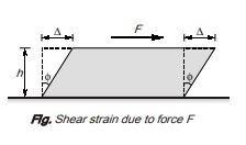
G = Shear stress/ Shear strain = τ/φ It is also called modulus of rigidity.
When a body is subjected to shearing stresses, the shape of the body gets distorted. The measurement of this distortion is done by angle of distortion. Under pure shear, the shape of the body get distorted but the volume remains same.
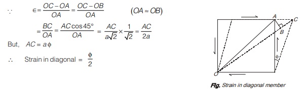
If under the shear, the shear strain is φ then the linear strain in the diagonal of the specimen is given by ∈ = φ/2 i.e. linear strain of diagonal is half of the shear strain in the body. It can be derived as given below:
Consider a cube of side ‘a’ subjected to shear and complimentary shear as shown in figure. Assuming that the strain are small and the angle ACB is 45° strain in diagonal OA is given as
Bulk Modulus (K): Bulk modulus is defined as the ratio of direct stress to the volumetric strain.
K = Direct stress/Volumetric strain = σ/∈v
Significance of Bulk modulus is with respect to compressibility. In 3D hydrostatic loading, 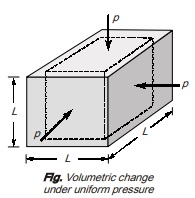
σx = σy = σz = p
and Volumetric strain, ∈v = ∆V/V
then Bulk modulus, 
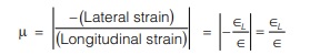
Poisson’s Ratio: Poisson’s ratio is defined as ratio of lateral strain to longitudinal strain within elastic limit under direct loading. It is represented by µ or 1/m.
In general, for engineering purposes, Poisson’s ratio varies from 0 to 0.5 but actual range is –1 to 0.5 The value of Poisson’s ratio of various materials are tabulated below:
| Material | Poisson’s ratio |
|---|---|
|
Aluminium |
0.33 |
|
Brass |
0.34 |
|
Bronze |
0.34 |
| Cast Iron |
0.2-0.3 |
|
Concrete |
0.1-0.2 |
|
Copper |
0.33-0.36 |
| Copper |
0.05-0.1 |
| Pure rubber and perfectly plastic material |
0.5 |
Relationship between Elastic Constants
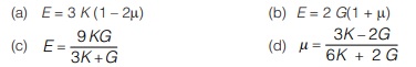
where, E = Young’s modulus of elasticity, G = Modulus of rigidity, K = Bulk modulus, µ = Poisson’s ratio
STRAIN ENERGY
Whenever a load is applied at the body, a strain is produced in the body due to which energy is absorbed in the body. The energy thus absorbed is known as strain energy. It is taken equal to work done by applied load in producing the strain. The strain produced can be due to:
(a) Gradually applied load
(b) Suddenly applied load
(c) Load with impact
Strain Energy Stored in Body when it is subjected to an Axial Load Gradually 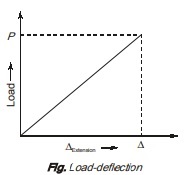
Consider the figure showing the load extension diagram of bar upto elastic limit when a tensile load ‘P’ is applied to bar. The ‘P’ increase gradually from zero to value of ‘P’ and with the increase in load P, deflection of body also increases gradually.
The load P will produce strain in body so strain energy will be stored in body which is equal to area of load deflection curve upto elastic limit.
Strain energy = Work done by load P in straining the body
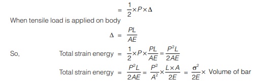
Here, σ2/2E is total strain energy per unit volume and known as modulus of resilience. Hence, strain energy per unit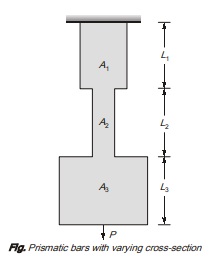 volume is equal to area of stress-strain curve upto elastic limit.
Case-1: Strain energy of prismatic bars with varying cross-sections
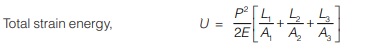
Case-2: Strain energy of non-prismatic bar with varying axial load.
Total strain energy ![]()
Strain Energy Stored in Body when the Load is Applied Suddenly 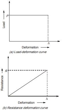
In this case, the value of load, P is constant throughout the deformation while deformation increases from zero to value ∆ as shown in figure (a)
However, the resistance force in the body is zero when deformation is zero and is equal to R when deformation reaches to its value ∆ as shown in figure (b).
So, work done by load, P = P × ∆
Work done by resistance force W = 1/2×R×∆
where resistance force R = σ × A
1/2×R×∆ = P × ∆
1/2×σ×A = P
σ = 2P/A
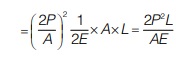
Now, strain energy stored in bar = σ2/2E×Volume of bar
Strain Energy Stored in a Body when Load is Applied with Impact 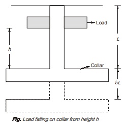
Consider a prismatic bar suspended freely with a collar at one end and a load P at height h from collar as shown in
figure. Let, when load ‘P’ is dropped on collar it elongates the bar by ‘δL
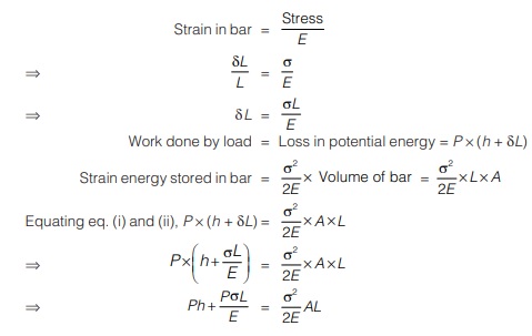
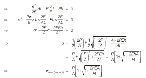
By using equation (ii) and value of σmax, we can find out strain energy.
Special case: When h = 0 i.e., it is analogues to case of sudden loading,
then, σ = P×2/ A as proved earlier.
<< Previous | Next >>
Must Read: What is Strength of Material?
Dear Aspirants,
Your preparation for GATE, ESE, PSUs, and AE/JE is now smarter than ever — thanks to the MADE EASY YouTube channel.
This is not just a channel, but a complete strategy for success, where you get toppers strategies, PYQ–GTQ discussions, current affairs updates, and important job-related information, all delivered by the country’s best teachers and industry experts.
If you also want to stay one step ahead in the race to success, subscribe to MADE EASY on YouTube and stay connected with us on social media.
MADE EASY — where preparation happens with confidence.
MADE EASY is a well-organized institute, complete in all aspects, and provides quality guidance for both written and personality tests. MADE EASY has produced top-ranked students in ESE, GATE, and various public sector exams. The publishing team regularly writes exam-related blogs based on conversations with the faculty, helping students prepare effectively for their exams.
