Simple Bending or Pure Bending
Consider a simply supported beam AB of length L subjected to moment M0 at its ends as shown in figures.
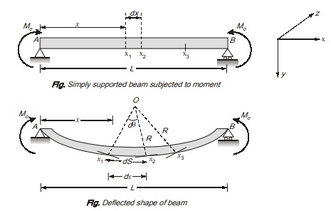
Consider an element of length dx at distance x from hinged support A. Due to applied moment, the beam will sag in a manner.
It can be seen in figure the element dx will be converted into an curve. Let the normal tangents at end point of element intersect a point O . This point O is known as centre of curvature. The distance Ox1 and Ox2 is known as radius of curvature. Let the angle made at centre of curvature by both the normal is denoted by dθ.
Curvature, C is defined as reciprocal of radius of curvature R i.e., C = 1/R
As from figure, ds = Rdθ
R = ds/dθ
Here, ds is length of arch x1x2
As, curvature is reciprocal of radius of curvature, so, from eq. (i)
Curvature, C = dθ/ds
For small deflection, as is usually case with beam, ds = dx
Hence, curvature C = dθ/dx
These equations are used to calculate normal or bending stress and strains in beam. Bending moment diagram for beam.
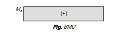
As clear from bending moment diagram, the beam is free from shear force. This type of bending in which there is no shear force is called as simple bending or pure bending. Bending in presence of shear force is known as non-uniform bending.
In pure bending, radius of curvature is constant at different sections of beam. For example, as the beam in figure is the case of pure bending, radius of curvature is R at section x3 also. As circular of curvature is constant, deflection curve of beam is circular.
Another case of pure bending can be a simply supported beam of length L subjected to concentrated loads as shown in figure
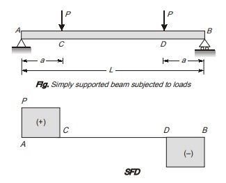
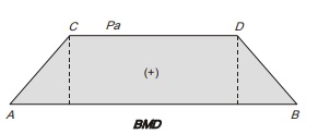
Its shear force diagram and bending moment diagram is shown in figure above.
As from shear force diagram, it is cleared that there is no shear force in region CD of beam. So in region CD, pure bending will occur due to which beam will be converted into an arc of circle.
Assumptions in Theory of Pure Bending
- Material of the beam is homogeneous, isotropic and linear elastic in which Hooke’s law is valid.
- The beam is straight before loading.
- Cross-section of beam is prismatic throughout the length.
- The plane section before bending remains plane after bending, it means, the longitudinal strain vary linearly from zero at neutral axis to maximum at the surface and longitudinal strain at any distance y is directly proportional to its distance (y) from neutral axis.
- Every layer of material is free to expand or contract longitudinally and laterally under stress and do not exert pressure upon each other. Thus, the Poisson’s effect at the interface of the adjoining differently stressed fibres are ignored.
- The value of Young’s modulus (E) for the material is same in tension and in compression.
- The section of the beam is symmetrical in the loading plane. If section is non symmetrical then twisting and warping may occur apart from bending.
Analysis of stress and strain in pure bending
a) Normal strain in beams
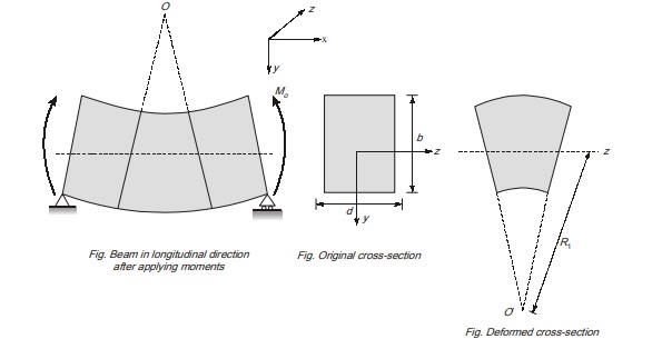
Consider a simply supported beam of length L subjected to moments at ends A and B as shown in figure.
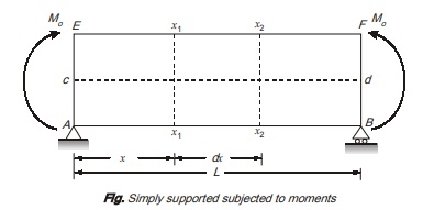
Take two section x1-x1 and x2-x2 which are dx length apart and section x1-x1 is at distance x from end A, as shown
Due to applied moments M0, the beam will sag in a manner as shown.
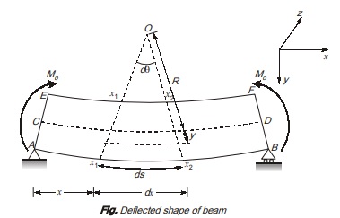
As it is case of pure bending, the elastic curve will be circular in shape.
Point O is the centre of curvature. Cross-section x1-x1 and x2-x2 will remain plane and normal to longitudinal fibres of beam so as to keep radius of curvature constant.
As it is evident , longitudinal fibres EF are shortened while fibres AB are elongated due to bending.
Thus top fibres are in compression while bottom fibres are in tension. Somewhere between top and bottom fibres, a surface of layer exist at which there is no change in length known as neutral layer as represented by CD. The intersection of neutral surface with any cross-sectional plane is called neutral axis.
Radius of curvature R is taken as distance from centre of curvature O to neutral layer.
As derived earlier,
Radius of curvature,
R = dx/dθ
Curvature,
C = dθ/dx
To calculate longitudinal strain, take a fibre GH at distance y from neutral layer CD as shown.
The length L1 of fibre GH = (R + y) dθ
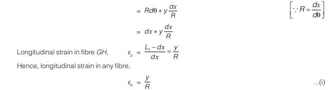
Here, y is the distance of fibre from neutral axis. Strains are positive below neutral axis and negative above neutral axis.
(b) Normal Stresses in beams
As per Hooke’s law, εx = σ/E
Here, σ is the bending stress in longitudinal direction and E is the Young’s modulus of elasticity.
So, by comparing eq. (i) and (ii)
σ/E = y/R
σ/y = E/R 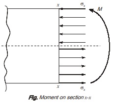
In simply supported beam, when subjected to downward M loading bending stresses are compressive above neutral axis while these are tensile below the neutral axis as shown in fig. (i).
Due to these stress, a moment is produced which is bending moment for the section and it acts along z-axis.
As the resultant force in x-direction is zero.
∫σx dA = 0…(iv) [∵ There is no other horizontal force]
When dA is small area element on cross-section on section.
By eq. (ii) σ/y = E/R
σ = Ey/R
∫Ey/R dA
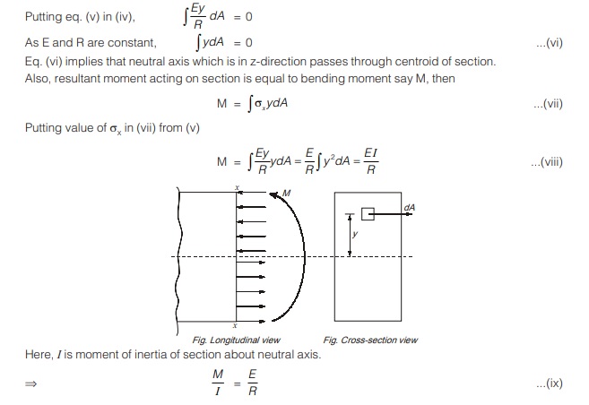
Hence, equation of pure bending, M/I = σ/y = E/R
(c) Transverse Strain
In figure shown, fibres are in compression above neutral surface or layer in longitudinal direction, so in transverse direction, fibres will elongate in transverse direction. Similarly, fibres below neutral surface are in tension in longitudinal direction, therefore, fibres will shorten in transverse direction due to Poisson’s effect. Consequently, a rectangular section will be transformed into a trapezoidal shape as shown:
Axial strain εx below neutral axis = y/R (As per eq. (i))
Therefore, transverse strain below neutral axis = νy/R
where ν is Poisson’s ratio.
As the curvature is very small in transverse direction, therefore radius of curvature R1 is higher than radius of curvature R is longitudinal direction. The relation between R1 and R can be given as R1 = R/ν
Limitations of Equation of Pure Bending
- Equation of bending is applicable when beam is free from shear force i.e. equation of bending is applicable to a member which is subjected to pure bending.
dM/dx = 0 - In general, beams are subjected to both bending moment and shear force. So theory of bending can be applied only for those sections where bending moments are maximum because at that section of maximum bending moment shear force is always zero. Hence, the condition of pure bending is supposed to be satisfied at those sections.
SECTION MODULUS (Z)
Equation of pure bending
M/I = σ/y
σ = M/I/y
For a given bending moment at y = ymax
σ = σmax
σmax = M/I/ymax
where I is moment of inertia of cross-section about neutral axis.
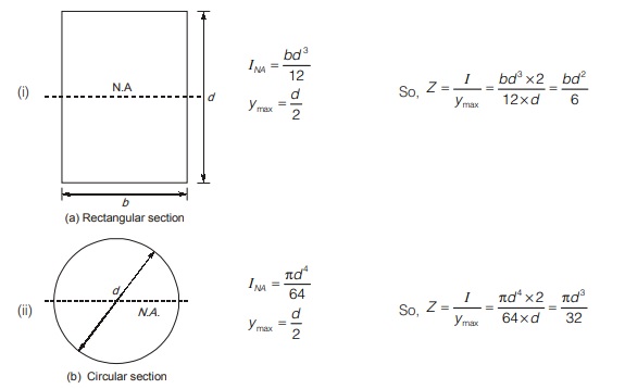
The term I/ymax is known as section modulus and is denoted by z.
So, section modulus, z = I/ymax
It represents strength of section. A section having high section modulus is stronger.
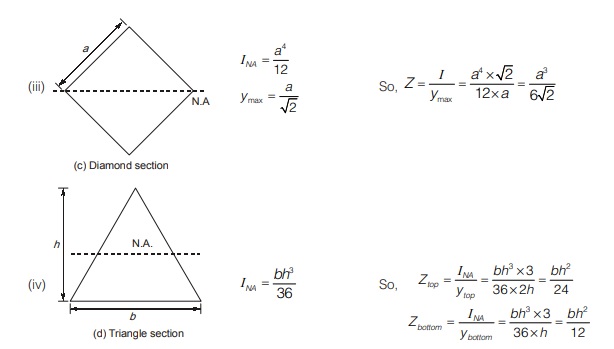
Section modulus for different cross-section
<< Previous | Next >>
Must Read: What is Strength of Material?
Dear Aspirants,
Your preparation for GATE, ESE, PSUs, and AE/JE is now smarter than ever — thanks to the MADE EASY YouTube channel.
This is not just a channel, but a complete strategy for success, where you get toppers strategies, PYQ–GTQ discussions, current affairs updates, and important job-related information, all delivered by the country’s best teachers and industry experts.
If you also want to stay one step ahead in the race to success, subscribe to MADE EASY on YouTube and stay connected with us on social media.
MADE EASY — where preparation happens with confidence.
MADE EASY is a well-organized institute, complete in all aspects, and provides quality guidance for both written and personality tests. MADE EASY has produced top-ranked students in ESE, GATE, and various public sector exams. The publishing team regularly writes exam-related blogs based on conversations with the faculty, helping students prepare effectively for their exams.
