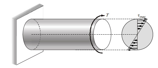
Shear Stress Distribution in Circular Section
Solid circular shaft
Hollow circular shaft 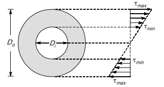
Di = internal diameter
Do = outer diameter
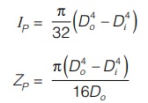
Thin circular tube with mean radius R 
Let t is thickness of tube
IP = Ar2
A = (2πR) × t
IP = (2πRt)R2 = 2πR3t
ZP = IP/Rmax = 2πR3t/ R = 2πR2t
The shear stress distribution is assumed uniform across the thickness and is given by
τ = T/ZP
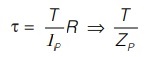
Composite circular shaft
Consider a composite circular shaft made from two materials whose modulus of rigidity are G1 and G2 In composite shaft, total torque T is shared by both shaft.
DESIGN OF SHAFT
Shaft is designed on the basis of following two criteria,
Strength criteria
τ≤τP
where, τP is permissible shear stress, τ is given as,
Stiffness criteria
θ≤θP
where, θP is permissible angle of twist.
Where, θ is given by,
T/IP = Gθ/L
θ = TL/GIP
The diameter of shaft will be greater value that is calculated by strength criteria or stiffness criteria.
SERIES COMBINATION OF SHAFT 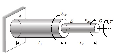
Series combination of shafts is done to transmit torque from one shaft to another shaft. For series connection couplings are used. Torque in all shaft connected in series will be equal.
T1 = T2 = T
Total angle of twist from A to C
θAC = θAB + θBC
θAC = TL1/G1IP1 + TL2/G2IP2
PARALLEL COMBINATION OF SHAFT 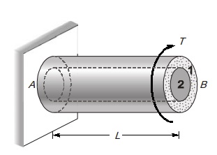
When one shaft is inside the other shaft, then two shafts are said to be connected in parallel. Parallel combination is done by providing keys between the shafts.
Let IP1 and G1 are properties of outer shaft and IP2 and G2 are properties of inner shaft.
Since there is no relative motion between them. Then angle of twist in both shaft will be equal.
θ1 = θ2
T1L/G1IP1 = T2L/G2IP2
The total torque is shared by both shafts. Hence
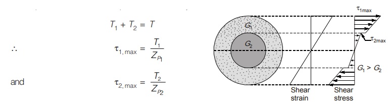
T1 + T2 = T
STRAIN ENERGY IN TORSION
The torsional strain energy of a shaft is equal to the work done in twisting
U = 1/2Tθ
where, T = Applied torque, θ = Angle of twisting
Due to torque, shear stresses are developed in metal. Hence strain energy due to torque can be represented in terms of shear stress.
Strain energy per unit volume = τ2/2G
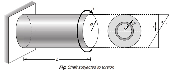
Consider a elemental tube of radius r and thickness dr and length L
Volume dV = (2πr)dr.L
∴ Strain energy stored in elemental volume dV is given by,
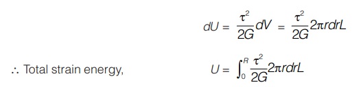
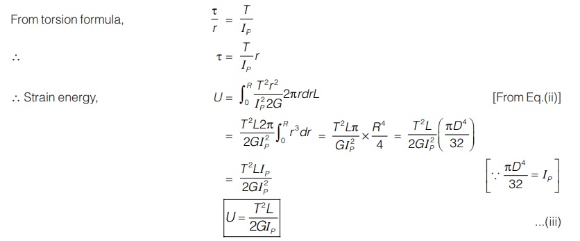
Case I: Strain energy in terms of torque
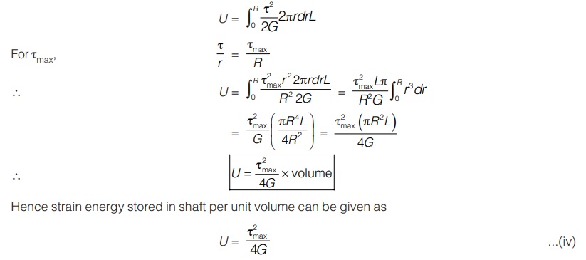
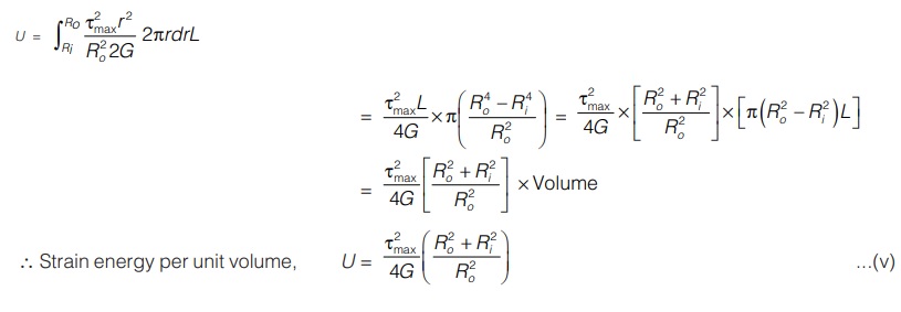
Case II: Strain energy in terms of τmax
Case III: Strain energy in hollow shaft in terms of τmax
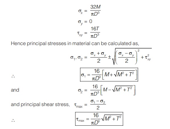
SHAFT SUBJECTED TO COMBINED BENDING MOMENT AND TWISTING MOMENT
When the shaft is subjected to combined bending moment and twisting moment, the maximum stresses induced in shaft are due to the combined effect of shear stress (τ) and bending stress (σb)
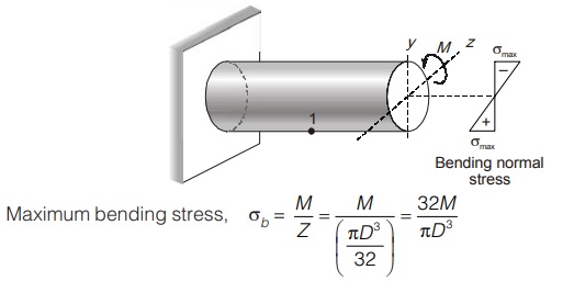
(i) Effect of pure bending
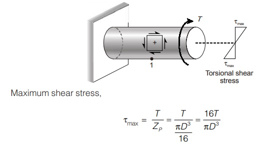
(ii) Effect of pure torsion
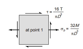
(iii) Combined effect of bending and twisting:
Under the effect of bending moment (M) and torsional moment (T), the stresses at extreme bottom or top fibre construct a stress element as shown in figure.
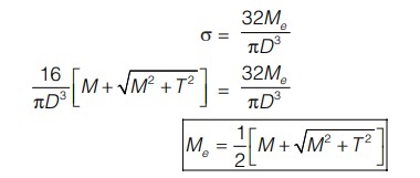
Equivalent Bending Moment
It is that bending moment which produces same maximum normal stress as produced by combined effect of bending and twisting.
If Me the equivalent bending moment. Then maximum normal stress produced will be
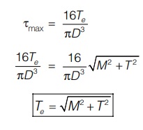
Equivalent Torque
It is that torque which produces same maximum shear stress as produced by combined effect of bending and twisting.
If Te be the equivalent torque then maximum shear stress produced will be
SHAFT SUBJECTED TO COMBINED AXIAL FORCE AND TORSIONAL MOMENT
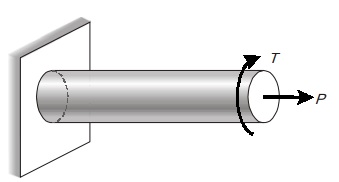
Consider a shaft subjected to an axial force and torsional moment as shown in figure.
Effect of axial force
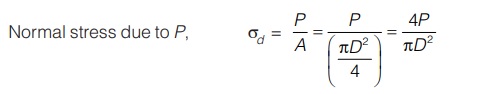
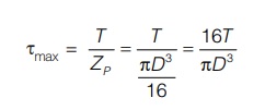
Effect of torsion
Combined effect of direct force and torsion
Consider any point on surface of shaft which will be in a state as shown below:
Therefore, principal stresses can be given as,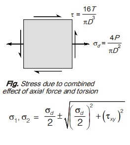
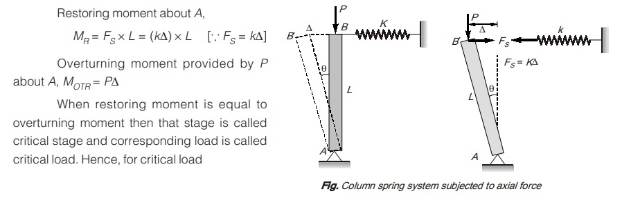
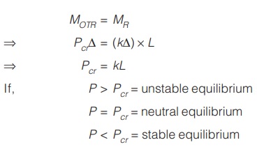
Elastic Instability and Critical Load
<< Previous | Next >>
Must Read: What is Strength of Material?
Dear Aspirants,
Your preparation for GATE, ESE, PSUs, and AE/JE is now smarter than ever — thanks to the MADE EASY YouTube channel.
This is not just a channel, but a complete strategy for success, where you get toppers strategies, PYQ–GTQ discussions, current affairs updates, and important job-related information, all delivered by the country’s best teachers and industry experts.
If you also want to stay one step ahead in the race to success, subscribe to MADE EASY on YouTube and stay connected with us on social media.
MADE EASY — where preparation happens with confidence.
MADE EASY is a well-organized institute, complete in all aspects, and provides quality guidance for both written and personality tests. MADE EASY has produced top-ranked students in ESE, GATE, and various public sector exams. The publishing team regularly writes exam-related blogs based on conversations with the faculty, helping students prepare effectively for their exams.
