PRINCIPAL STRESSES AND MAXIMUM SHEAR STRESS
(a) Principal Stress 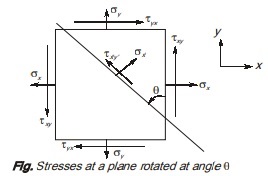
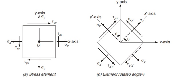
Consider a planar stress element subjected to normal and shear stress as shown below. Normal stress and shear stress on a plane inclined at an angle θ with vertical plane are represented by σx′ and τx′y′ as shown below.
When variation of normal and shear stress with angle of rotation θ is studied, it can be shown.
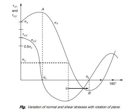
As we can see, when plane is rotated continuously in anticlockwise direction, normal stress at a point σx′ attains a maximum value and minimum value at point A and point B respectively known as major principal stress and minor principal stress represented by σ1 and σ2 respectively. It is to noted that when normal stress is maximum and minimum shear, stress is zero on these planes.
Expression For principal stresses:
σx’ = (σx + /2) + (σx – σy/2) cos2θ + τxy sin2θ ………(i)
As the principal stresses are maximum and minimum value of normal stress,
dσx′/dθ = 0 …….(ii)
dσ′/dθ = (σx – σy/2) – 2sin2θ + 2τxy cos2θ ………(iii)
tan2θP = 2τxy/σx – σy ……..(iv)
Angle θP defines the orientation of principal planes.
These are the planes on which principal stresses acts. From eq. (iv), θP has two values, one is from 0 – 90° and other is from 90° – 180°. Both value differ by a value of 90°
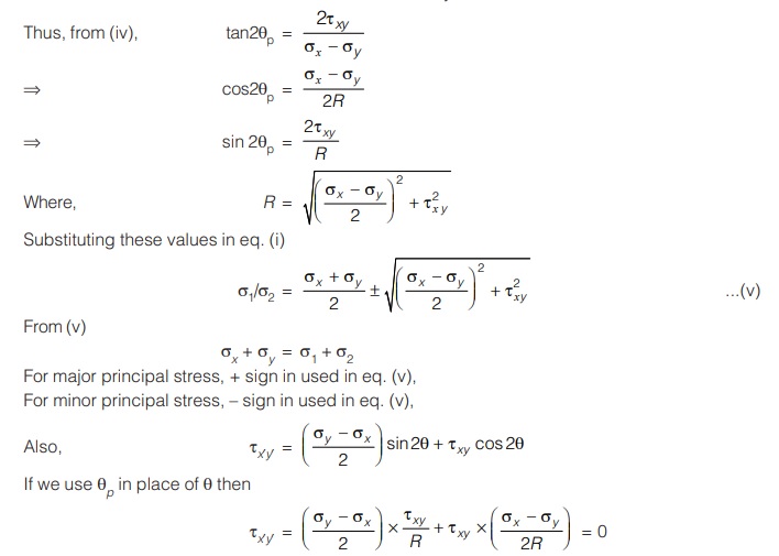
Hence, it can be inferred that on principal plane, the value of shear stress is zero.
• In uniaxial and biaxial stress element, principal planes are x and y plane themselves.
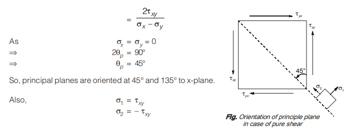
• In case of pure shear
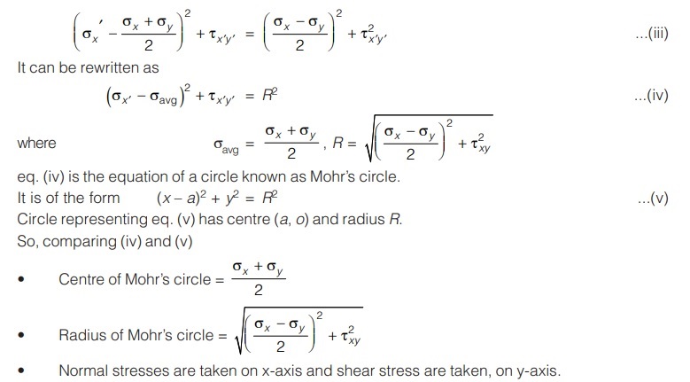
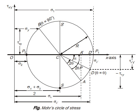
MOHR’S CIRCLE
(a) For Plane Stress:
The transformation equation for plane stress are:
σx = (σx + σy/2) = (σx – σy/2) cos2θ + τxy sin2θ …..(i)
τxy = (σx – σy/2) sin2θ + τxy Cos2θ ………(ii)
These equations can be represented in graphical form Known as Mohr’s circle. This method can be very helpful in determining the stresses on an included plane at point in body.
These equations are equation of circle in parametric form where angle 2θ is the parameter. Squaring both sides of equation and then eliminating the parameter by adding the equations.
we get.
(a) Construction of Mohr’s Circle
Sign convention
(i) Normal stresses: Tensile normal stresses are plotted in + s x direction.
Compressive normal stresses are plotted in –x direction.
(ii) Shear stress:
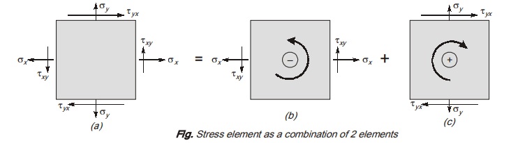
Stress element can be thought off as combination of two stress element as shown.
There is an anticlockwise moment about centre due to shear stress, so coordinates of this element are (σx’ –τxy) on Mohr’s circle.
(a) Steps to construct Mohr’s circle for a plane stress element
Consider a planar stress element as shown in figures.
Steps:
- Take σ’x on x-axis and τx’y’ on y-axis as shown.
- Locate the centre of circle having coordinate (σavg = σx + σy/2,0)
- Locate a point A having coordinates (σx , σxy) representing the stress condition of x-face of stress element in figure a(1). [–ve sign with τxy is used as per our sign convention]
- Locate a point B having coordinates (σy, τxy) representing the stress condition of y-face of stress element in figure a (ii). Line joining point A and B will pass through point C.
Radius of circle, R as derived earlier is 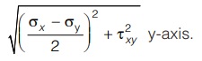
Thus a circle with centre C and radius R can be drawn in figure.
We have to determine stress on inclined face of element oriented, at angle θ as shown in figure a(ii) using Mohr’s circle method.
The point on Mohr circle corresponds to a plane at zero inclination i.e. at θ = 0
Take a point D on Mohr’s circle at angle 2θ in anticlockwise direction from radius CA. Point D has coordinates (σ’x, – σx’y’).
Let α is angle between radius (i) and x-axis. Then from geometry.
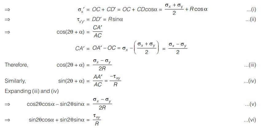
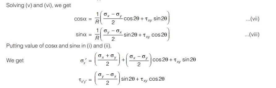
Which are same as equations for stress transformation.
Hence a point D on Mohr circle defined by angle 2θ represent the stress condition on x′ face of stress element, defined by angle θ.
Hence it can be said that when we rotate the stress element in anticlockwise direction by angle θ, the point on Mohr’s circle will be at angle 2θ in anticlockwise direction.
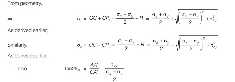
(b) Principal Stresses on Mohr’s Circle
In Mohr circle of stress figure cut the x-axis at two points namely P1 and P2. At these points, shear stresses are zero. Also, normal stress is maximum at point P1 and minimum at point P2. Hence these planes are principal planes and normal stresses on these planes are principal stresses.
Therefore, Coordinates of point P1 = (σ1, 0)
Coordinates of point P2 = (σ2, 0)
As stated earlier, angle between x-face of stress element and principal plane is θp1, therefore angle between radius CA(θ = 0) and point P is 2θP.
(c) Maximum Shear Stress
We know that plane of maximum shear stress is at 45° to principal plane, therefore on Mohr’s circle, plane of maximum shear stress will correspond to point S and S′ which are at 90° to principal planes.
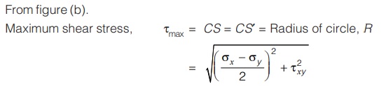
As derived earlier.
Hence, we can find stresses on any inclined planes, principal stresses, principal planes, maximum shear stress by constructing Mohr’s circle for stress element.
<< Previous | Next >>
Must Read: What is Strength of Material?
Dear Aspirants,
Your preparation for GATE, ESE, PSUs, and AE/JE is now smarter than ever — thanks to the MADE EASY YouTube channel.
This is not just a channel, but a complete strategy for success, where you get toppers strategies, PYQ–GTQ discussions, current affairs updates, and important job-related information, all delivered by the country’s best teachers and industry experts.
If you also want to stay one step ahead in the race to success, subscribe to MADE EASY on YouTube and stay connected with us on social media.
MADE EASY — where preparation happens with confidence.
MADE EASY is a well-organized institute, complete in all aspects, and provides quality guidance for both written and personality tests. MADE EASY has produced top-ranked students in ESE, GATE, and various public sector exams. The publishing team regularly writes exam-related blogs based on conversations with the faculty, helping students prepare effectively for their exams.

