What is a Composite Beam in Strength of Materials?
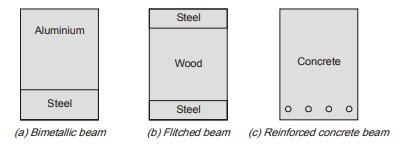
A beam that is built from more than one material is known as composite beams. Example are bimetallic
beams, flitched beams and reinforced concrete beam as shown.
The materials in composite beam can be:
(a) Simply placed over one another
(b) Rigidly connected
a) Simply placed over one another
Consider a beam section in which two different materials (1) and (2) are used to make the section with their Young’s modulus of elasticity E1 and E2 respectively. There is no bond between material (1) and (2) so they will bend independently about their own neutral axis and their stress distribution diagram is shown in figure.
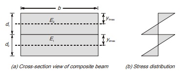
However, it is assumed that radius of curvature at junctions of both the materials is same So, R1 = R
From flexure formula, R = Ey/σ
(b) Rigidly connected
When different materials are rigidly connected to make the cross-section, then there is a common neutral axis and they behave like a single beam. But the position of neutral axis will not be the centroid of section because materials are different so the assumption of homogeneity does not apply here.
However, if by any method, section is converted in terms of any one material, then neutral axis will coincide with the centroid of equivalent section. In such types of beam bending strain diagram is linear hence strain in two material at a given vertical distance from NA will be same which is called strain compatibility condition. To convert one section into other, concept of modular ratio is used which is defined as ratio of modulus of elasticity of both the materials. In this method, width of one material is multiplied by modular ratio. Thus two types of method that can be used to analyse composite beam in which materials are rigidly connected are illustrated below with the help of analysis of flitched beam.
FLITCHED BEAM
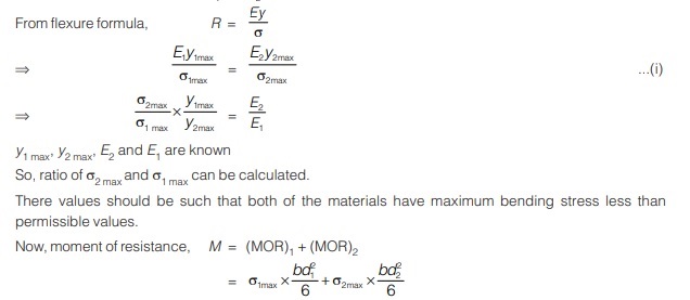
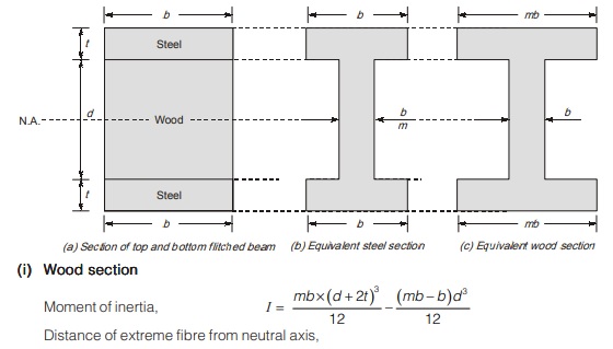
Top and bottom flitched beam
Method-1
By strain compatibility; strain in steel = Strain in wood
εs = εw
σs/Es = σw/Ew
σs/σw = Es/Ew = m (modular ratio)
At same level, if stress in steel is σs, then corresponding stress in wood will be
σw = σs/m
σs = mσw
Let permissible stress in wood is σw
Permissible stress in steel is σs’max
Stress in steel at junction of wood is σs
Then, moment of resistance of wood section,
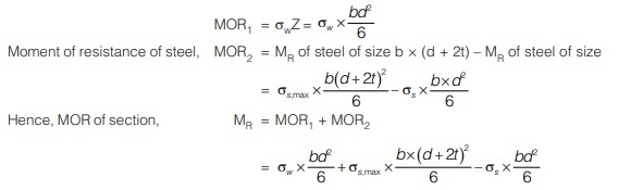
Method-2
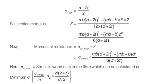
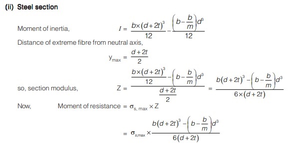
Moment of resistance of top and bottom flitched beam can be calculated by converting heterogeneous section into either equivalent wooden section or steel section as shown in figure.
Side flitched beam
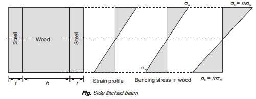
Moment of resistance of wood, MORw = σw x bd2/6
Moment of resistance of steel, MORs = σs x 2td2/6
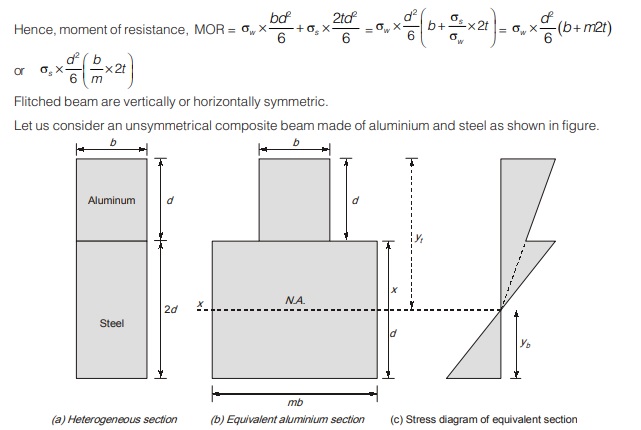
Modulus of elasticity of aluminium = Ea
Modulus of elasticity of steel = Es
Modulus ratio, m = Es /Ea
Let the heterogeneous section is converted into equivalent aluminium section by multiplying width of steel section by modulus.
Permissible stress in aluminium = σa
Permissible stress in steel = σs
First of all, we have to find moment of inertia of equivalent aluminium section about its neutral axis.
Location of neutral axis from top = ∫ydA/∫dA
After calculating location of neutral axis, let the moment of inertia calculated is I.
Let, the distance of top and bottom fibre of equivalent aluminium section from neutral axis is yt and yb respectively as shown.
Its section modulus will be different in tension and compression as the section is unsymmetrical.
Maximum stress at top of section = σa
Maximum stress at bottom of section,
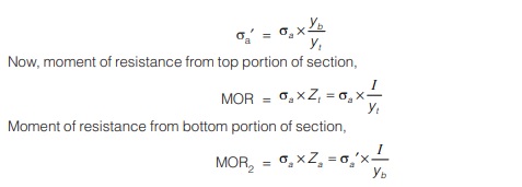
Moment of resistance of section is taken as lesser of MOR1 and MOR2
<< Previous | Next >>
Must Read: What is Strength of Material?
Dear Aspirants,
Your preparation for GATE, ESE, PSUs, and AE/JE is now smarter than ever — thanks to the MADE EASY YouTube channel.
This is not just a channel, but a complete strategy for success, where you get toppers strategies, PYQ–GTQ discussions, current affairs updates, and important job-related information, all delivered by the country’s best teachers and industry experts.
If you also want to stay one step ahead in the race to success, subscribe to MADE EASY on YouTube and stay connected with us on social media.
MADE EASY — where preparation happens with confidence.
MADE EASY is a well-organized institute, complete in all aspects, and provides quality guidance for both written and personality tests. MADE EASY has produced top-ranked students in ESE, GATE, and various public sector exams. The publishing team regularly writes exam-related blogs based on conversations with the faculty, helping students prepare effectively for their exams.
