Beam of Uniform Strength
For an economical design, the section of the beam may be reduced towards the support, as bending moment decreases towards the supports. The beam may be designed such that at every section, the extreme fibre stress reaches the permissible stress. A beam so designed is called beam of uniform strength this 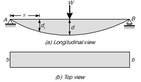 can be done by.
(i) Uniform width varying depth
(ii) Uniform depth varying width
(i) Beam of constant width: Let width of beam is constant throughout the span, but depth of beam is variable, such that the depth of beam at a distance x from support A is dx and at mid span it is equal to d.
Section modulus at a distance x from A is given by
Zx = bd2x/6
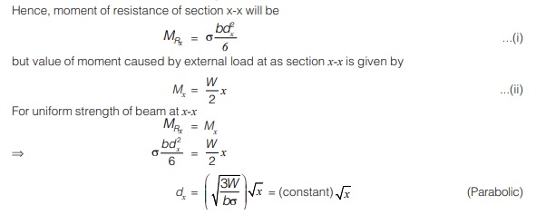
(ii) Beam of constant depth: Let depth of beam is constant throughout the span but width of beam is variable such that the width of beam at a distance x from support A is bx and at mid span it is equal to b.
at a distance x from A, section modulus is given by
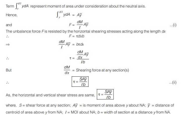
SHEAR STRESS IN BEAMS
Assumptions:
- Material is homogeneous and elastic.
- Material obeys Hooke’s law.
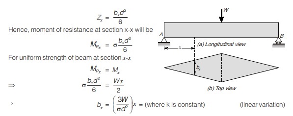
- Shear stress is assumed constant along width and variation is considered along depth of section. Consider a beam of rectangular cross-section of size b × d subjected to shear force V and two planes x1-x1 and x2-x2 are taken parallel to neutral axis. The direction of shear stress is assumed parallel to direction of shear force as shown.
As we know that shear stress on one side of element is accompanied by complementary shear stress of equal magnitude acting on the perpendicular face on an element, hence equal horizontal shear stress will act on horizontal face as shown in figure (b).
Moreover, top and bottom fibres of beam can’t have horizontal shear stress, so vertical shear stress will also vanish at top and bottom of beam.
Variation of Shear Stress in Beam
Consider a small portion of length dx at a distance x from A between section x1 and x2. Let beam is subjected to uniformly distributed load of intensity w per unit run, which produces moment M at section x1 and M + dM at section x2. The portion above NA will be in compression and portion below NA .
Shear Stress Distribution in Rectangular Section 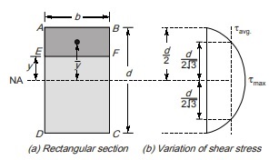
Consider a beam of rectangular section of width b and depth d as shown in figure.
Shear stress for an element at a distance y above NA is given by
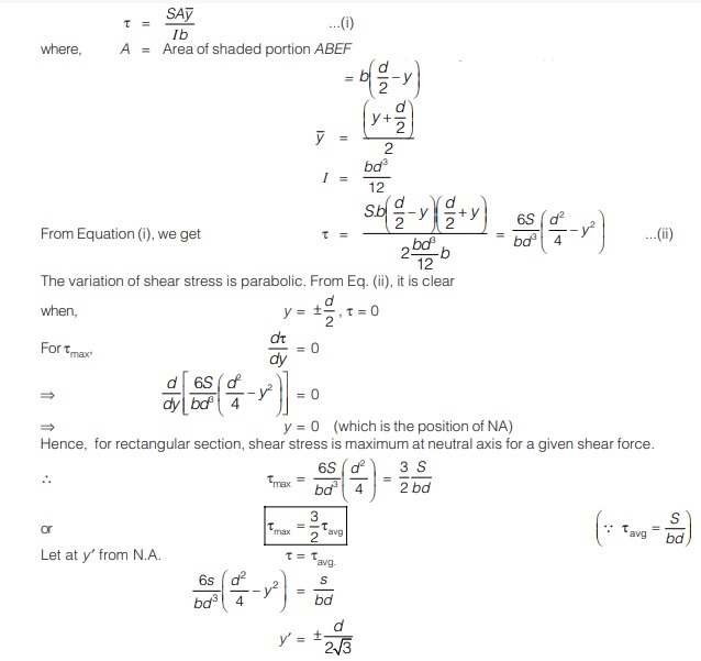
Let, M = bending moment at x1-x1
M + dM = Bending moment at x2-x2
S = Shear force at x1-x1
S + dS = Shear force at x2-x2
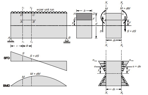
Consider an elementary strip at a distance y from the NA. Let σ is bending stress at section x1-x1 at a distance y from the NA and σ + dσ is at same location at section x2 – x2. By bending equation,
SHEAR CENTRE
Consider a singly-symmetric cross-section cantilever beam of length subjected to a downward concentrated load P.
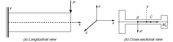
Its cross section i.e. I-section with unequal flanges is shown in figure (b). Due to action of load P at any section, two stress resultant exist:
(a) Bending moment Mz about z axis.
(b) Shear force V acting in y direction.
Bending moment Mz is resultant of normal stresses on cross-section while shear force V is resultant of shear stress. While deriving shear stresses, we have used variation of bending moment therefore distribution of shear stresses is affected by distribution of normal stresses.
Shear force should have its line of action passing through a point S lying on z-axis. This point S is known as shear centre and it does not coincide with centroid except in cases of doubly symmetric section.
If the resultant of shear stress i.e. shear force does not pass through shear centre, then section will be subjected to a torsional moment in addition to shear force, it can be said that a lateral load acting on a beam will produce bending without twisting only when it passing through shear centre.
PLANE STRESSES
Consider a rectangular stress element showing normal stress and shear stress on a point in a beam subjected to both bending and shear as shown in figure (a).
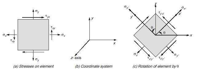
Right hand face of element is taken in positive x-direction. Similarly top face of element is taken in positive y-direction.
As, the element is subjected to stresses parallel to x and y axis, so it is a case of plane stress. As we know that shear stress on perpendicular plane is equal, therefore τxy = τyx
Now, the stress element is rotated through angle θ in anti-clockwise direction about z axis such that normals to right and top face are parallel to x′ and y′ axis.
Coordinate axes x′ and y′ will also be at angle θ to original x and y axis.
It is known as transformation of axes or stress transformation. Let the normal and shear stresses on rotated element are represented by σx′, σy′ , τx′y’ and τy′x’ respectively. Note that τx′y’ and τy′x’ are also equal in magnitude.
Stresses acting on rotated element can be expressed in terms of stress on original element using equations of static equilibrium. For this, consider a wedge shaped element as shown in figure below.
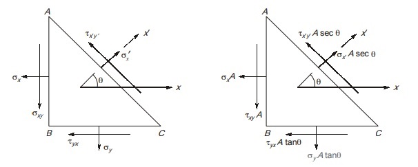
To use equations of static equilibrium, we need to rewrite stresses on rotated element in terms of forces acting on the faces of element. In, the figure, A is the area of face AB on which normal and shear stresses are acting. Then area of face BC will be A tanθ and area of face AC will be A secθ
By equations of static equilibrium ΣFx = 0
σx′Asecθcosθ – τx′y’Asecθsinθ – σxA – τyxtanθ = o
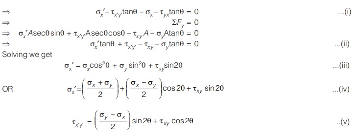
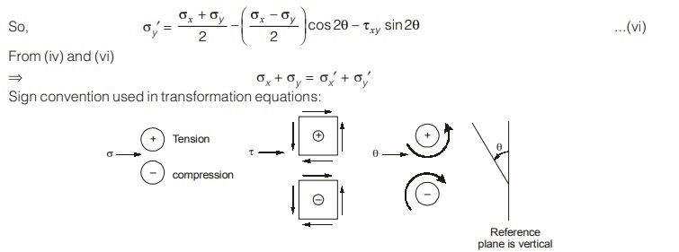
The equation for σx’ and τx′y’ are known as transformation equations.
Normal stress σy’ acting on a plane normal parallel to y′-axis is calculated by putting (90 + θ) in place of θ in eq. (iii).
Special Case:
(a) Uniaxial Stress 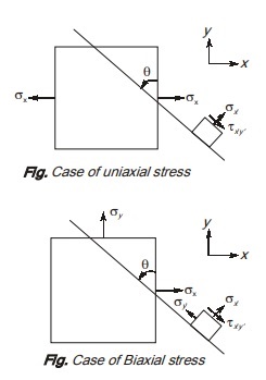
If an element xy is subjected to normal stresses in one direction only without shear stress then it is a case of uniaxial stress. Putting σy and τxy equals to zero in eq. (iv) and (v), we get,
Normal stress on plane rotated at angle θ, σx’ = σx cos2 θ.
Shear stress on plane rotated at angle θ, τx′y’ = –σx sinθ cosθ.
(b) Biaxial stress
If an element is subjected to normal stress in both x and y direction without shear stress, then it is a case of biaxial
stress.
Putting τxy equals to zero in eq. (iv) and (v), we get Normal stress on plane rotated at angle θ,
σx’ = (σx + /2) + (σx – σy/2) cos2θ
Shear stress on plane rotated at angle θ, τx′y’ = (σx – σy/2) sin2θ
<< Previous | Next >>
Must Read: What is Strength of Material?
Dear Aspirants,
Your preparation for GATE, ESE, PSUs, and AE/JE is now smarter than ever — thanks to the MADE EASY YouTube channel.
This is not just a channel, but a complete strategy for success, where you get toppers strategies, PYQ–GTQ discussions, current affairs updates, and important job-related information, all delivered by the country’s best teachers and industry experts.
If you also want to stay one step ahead in the race to success, subscribe to MADE EASY on YouTube and stay connected with us on social media.
MADE EASY — where preparation happens with confidence.
MADE EASY is a well-organized institute, complete in all aspects, and provides quality guidance for both written and personality tests. MADE EASY has produced top-ranked students in ESE, GATE, and various public sector exams. The publishing team regularly writes exam-related blogs based on conversations with the faculty, helping students prepare effectively for their exams.
