Preconsolidation Pressure
The maximum pressure to which an overconsolidated soil had been subjected in the past is known as the preconsolidation pressure or over-consolidation pressure (σc) . When a soil specimen is taken from a natural deposit, the weight of the overlying material (over-burden) is removed. This causes an expansion of the soil due to a reduction in pressure. Thus the specimen is generally pre-consolidated or over-consolidated. When the specimen is loaded in the consolidation test, the initial portion AB of the compresion curve ABCD is actually a recompression curve. Consequently, the initial portion AB is relatively flat. It is followed by a straight line CD with a steep slope which indicates the compression of a virgin (normally consolidated) soil.
In the transition range BC, the slope gradually changes. The preconsolidation pressure (σc) falls in this range. It can be obtained using the method given by Casagrade.
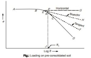
The procedure consists of the following steps:
- Determine the point E on the curve where the curvature is maximum, i.e., the radius of curvature is minimum.
- Draw the tangent EF to the curve at E.
- Draw horizontal line EG at E.
- Bisect the angle between the tangent EF and the horizontal EG, and draw the bisector EH.
- Produce back the straight line portion CD of the curve and determine the point of intersection P of the bisector EH and the backward extension of CD.
- Draw the vertical PJ through P which cuts the log σ -axis at J. The point J indicates the preconsolidation pressure σc .
- The vertical PJ cuts the curve at point K. The portion ABK of the curve represents the recompression curve and the portion KCD as the virgin compression curve.
Length of Drainage Path
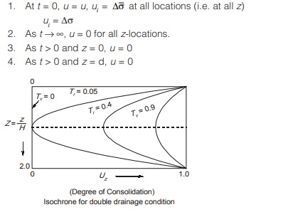
- In case of double drainage, there are two drainage surfaces, one at top and another at bottom of consolidating layer.
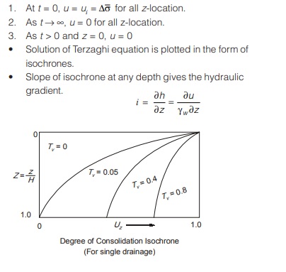
Length of drainage path, d = H0 / 2 …(For two way) - In case of single or one-way drainage, drainage surface is provided either at top or bottom.
Length of drainage path, d = H0 …(For one-way) - During the process of consolidation, thickness of soil layer decreases. Hence length of drainage path also changes. So, for accurate computation average drainage length must be taken.
Let, di = Initial drainage length
di = Final drainage length after consolidation
davg = di + df / 2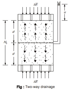
Double Drainage System:
Single Drainage System
Degree of Consolidation
- It refers to the percentage of primary consolidation at any instant of time. At any instant it is represented by U.
- At the beginning of consolidation, degree of consolidation is 0 or 0%.
- At the end of consolidation, when expulsion of pore water stops, degree of consolidation is 1 or 100%.
0% ≤ U ≤ 100% - Degree of consolidation can be computed as follows:
- In terms of settlement:
Let ∆H be the ultimate consolidation settlement corresponding to U = 100%.
Degree of consolidation at any time ‘t ’ when settlement is ∆h, is
U % = ∆h / ∆H x 100 - In terms of void ratio:
Let e0 be the initial void ratio at the centre of soil when U = 0%
Let e100 is be the final void ratio after completion of consolidation at U = 100%.
At any intermediate time ‘t ’, void ratio is ‘e’, then degree of consolidation is given by,
U % = e0 – e / e0 – e100 x 100 - In terms of excess pore pressure:
Let initially excess pore pressure be ui and let after any time ‘t ’ the excess pore pressure be u, then degree of consolidation is given by
U % = ui – u / ui x 100
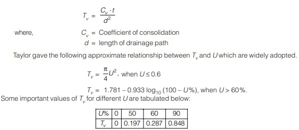
Time Factor (Tv)
This is a non-dimensional parameter, which is directly proportional to time elapsed ‘t’ for a particular soil and inversely proportional to the square of length of drainage path. This is given by
<< Previous | Next >>
Must Read: Soil Mechanics and Foundation Engineering
Dear Aspirants,
Your preparation for GATE, ESE, PSUs, and AE/JE is now smarter than ever — thanks to the MADE EASY YouTube channel.
This is not just a channel, but a complete strategy for success, where you get toppers strategies, PYQ–GTQ discussions, current affairs updates, and important job-related information, all delivered by the country’s best teachers and industry experts.
If you also want to stay one step ahead in the race to success, subscribe to MADE EASY on YouTube and stay connected with us on social media.
MADE EASY — where preparation happens with confidence.
MADE EASY is a well-organized institute, complete in all aspects, and provides quality guidance for both written and personality tests. MADE EASY has produced top-ranked students in ESE, GATE, and various public sector exams. The publishing team regularly writes exam-related blogs based on conversations with the faculty, helping students prepare effectively for their exams.
