Classification of Rivers
What is the classification of river system in India?
Rivers are mainly classified on the basis of the topography of the river basin in following manners:
- River in hills
- River in Alluvial plains
- Tidal rivers
(1.) River in Hills
River generally takes off from mountains and flow through hilly regions before traversing the plains.
Rivers in hills are subdivided into
- Rocky river stage
- Boulder river stage
(2.) River in Alluvial Plains
River in alluvial flood plains can assume a number of forms based on the properties of their banks, the amount, size and type of sediment that they carry. Geometry of river in alluvial flood plains changes over time. Geometrical changes are caused by erosion and deposition of sediments.
Common examples are meandering rivers, braided rivers and deltaic rivers.
(3.) Tidal Rivers
A tidal river is the river whose tail reaches adjoining the oceans are affected by the tides in the ocean. Ocean water enters the river during flood tide and goes out during the ebb tide. Rivers undergoes periodical rise and fall in its water level depending upon nature of tide. Estuaries are common example of tidal river.
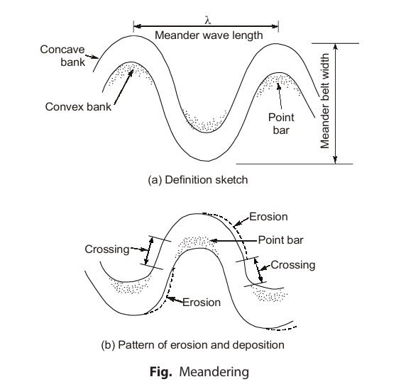
Meandering Phenomena
Meandering
Meandering is considered a wave phenomena. A meander is formed when moving water in a stream erodes the outer banks and widens its valley and the inner part of the river has less energy and deposits what it is carrying. A meandering channel tends to be deeper towards the concave bank and progressively gets shallower towards convex bank.
Causes of Meandering
Factors responsible for meandering are:
- Size and grade of sediments that make up the river beds.
- Extra turbulence generated by transported sediments during floods.
- Valley slope
- Bed slopes and side slope of the river channel
When the quantity of silt is in excess of quantity required for stability of the river, the river starts building up its slope by depositing silt on its bed. Increase in river slope increases the width of the channel if banks are nonresistant. One bank is likely to be attacked more than the other bank leading to more and more flow towards one bank compared to other bank. Concave bank goes on eroding while convex bank goes on silting leading to the formation of meanders.
Components of Spillway
Main components of spillway are:
- Control structure
- Conveyance structure
- Terminal structure
- Entrance and exit channel
(a) Control structure: It controls and regulates the outflow from the It is usually located at the upstream end of the spillway and consists of some orifice or overflow crest. (In some cases, the control may be at the downstream end). In most of the cases, the control structure consists of weir which may be sharp (or narrow) crested, ogee shaped or broad crested.
(b) Conveyance structure: The outflow released through the control structure is usually conveyed to the downstream river channel through a discharge channel or Conveyance structure are, in general, the downstream face of the dam or an underground tunnel excavated through one of the abutments.
(c) Terminal structure: When water flows from reservoir level to the downstream river level, the static energy is converted into kinetic energy. This kinetic energy, if not properly dissipated, may cause scour near the toe of the dam, which can cause damage to the dam, spillways and other Therefore, suitable energy dissipaters are usually provided so that the kinetic energy is dissipated. Energy dissipaters can be hydraulic jump basin, roller buckets etc.
(d) Entrance and exit channel: Entrance channel conveys water from the reservoir to the control structure. Exit channel conveys water flow from the terminal structure to the stream channel downstream of the In general, entrance and exit channels are needed in spillways which are placed along the abutments or located near saddles or ridges.
Hydraulic Jump Formation
A hydraulic jump takes place when a stream of water moving with high velocity and low depth (i.e. super critical flow) strikes another stream of water (i.e. sub-critical flow). It is generally accompanied by a large scale turbulence which is the reason for dissipation of kinetic energy of super-critical flow.
Depending upon the incoming Froude number, jump on a horizontal floor can be classified as follows:
- For F1 = 1, the flow is critical and jump can’t be formed.
- For F1 = 1 to 7, jump is known as undular jump as water surface starts showing undulations.
- For F1 = 1.7 to 2.5, jump is known as weak jump. In this type of jump, a series of small rollers develop on surface of jump but downstream water surface remain Energy loss is low in this jump.
- For F1 = 2.5 to 4.5, the jump is known as oscillating jump. In this type of jump, on oscillating jet enters jump bottom to surface and backs again with no A large wave of irregular period is produced by each oscillation. These large waves are common in canals, can travel for large distances and cause unlimited damage.
- For F1 = 5 to 9.0, jump is balanced and performance of jump is best. It is known as steady jump.
- For F1 = 9 and larger, jump is known as strong jump.
The approximate percentage loss of energy for various values of incoming Froude number i.e. F1 is given in table below:
| F1 | % loss of energy |
|---|---|
| 2.5 | 17 |
| 4.5 | 45 |
| 9 | 70 |
| 14.0 | 80 |
| 20 | 85 |
As we know, in a hydraulic jump
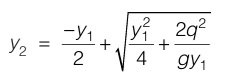
where, y1 and y2 are pre and post jump depth of flow respectively q is discharge intensity i.e. discharge per unit width.
Consider the section of a spillway as shown in figure below:
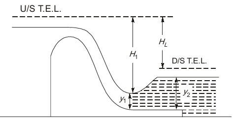
In figure, it can be seen that depth y1 is fixed for a given discharge intensity q and depth of flow y2 after jump can be calculated by equation (i). But it is not necessary that tail water level at downstream end is equal to post jump depth y2 calculated by equation (i).
The tail water level depends upon hydraulic dimensions and slope of river channel below.
Therefore, depending upon the tail water level and post jump depth y2 calculated by equation (i), total 5 number of cases can occur which are discussed in next section along with the energy dissipator that is used for each case.
Dear Aspirants,
Your preparation for GATE, ESE, PSUs, and AE/JE is now smarter than ever — thanks to the MADE EASY YouTube channel.
This is not just a channel, but a complete strategy for success, where you get toppers strategies, PYQ–GTQ discussions, current affairs updates, and important job-related information, all delivered by the country’s best teachers and industry experts.
If you also want to stay one step ahead in the race to success, subscribe to MADE EASY on YouTube and stay connected with us on social media.
MADE EASY — where preparation happens with confidence.
MADE EASY is a well-organized institute, complete in all aspects, and provides quality guidance for both written and personality tests. MADE EASY has produced top-ranked students in ESE, GATE, and various public sector exams. The publishing team regularly writes exam-related blogs based on conversations with the faculty, helping students prepare effectively for their exams.
