Canal Lining
By lining of canal, we mean that the earthern surface of the canal is lined with a stable lining surface (such as concrete, tiles, asphalt etc.).
Necessity of Lining of Canal
Lining of canal is necessary:
- to minimize the seepage losses in canal,
- to increase the discharge in canal section by increasing the velocity,
- to prevent the erosion of bed and sides of canals,
- to reduce maintenance of canals,
- to retard growth of weeds.
Advantages of Lining of Canal
The main advantages of lining a canal are:
- prevents seepage loss and hence more area can be employed for irrigation,
- helps in prevention of water logging,
- provides a smooth surface,
- increased velocity in a canal minimizes the losses due to evaporation,
- increased velocity in a canal prevents silting of the canal,
- increases available head for power generation as a flatter gradient can be provided,
- canal lining assures economical water distribution,
- prevents water to come into contact with harmful salts during transit.
Disadvantages of Lining of Canal
The disadvantages of lining of canal are:
- It requires heavy initial investment.
- It is difficult to repair damaged lining.
- It is very difficult to shift the outlets very often (as linings are permanent).
Types of Lining of Canal
Important types of canal lining which are commonly adopted are:
-
Hard surface linings:
- Cement concrete lining
- Shotcrete or plaster lining
- Cement concrete tile lining or Brick lining
- Asphaltic concrete lining
- Stone blocks lining (or undressed stone lining)
-
Earth type lining:
- Soil cement lining
- Sodium carbonate lining
- Clay puddle lining
-
Buried and protected membrane type lining:
- Prefabricated light membrane lining
- Bentonite soil and clay membrane lining
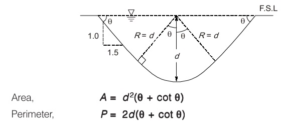
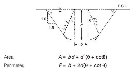
Procedure for Designing a Lined Channel
- Find out the value of hydraulic mean depth R by the help of Manning’s equation (Limiting velocity V, Rugosity coefficient n and longitudinal slope S should be known in advance)
- Find area of cross section of canal from equation of continuity
A = Q/V
- Find out the wetted perimeter of the cross section by the formula R = A /P.
- Use the formula for triangular channel section and trapezoidal channel section as per the discharge values and depth d
(a) Triangular channel section
(b) Trapezoidal channel section
Requirement of Good Site for Construction of Dams
- Suitable foundation should be available at the dam site.
- Length of dam should be as small as possible from economic point of view and for a given height it should store a large volume of water.
- River cross-section at the dam site should preferably be narrow to reduce the length of the dam. However it should open out upstream to provide a large basin for reservoir.
- Major portion of the dam should be on a high ground (reduces cost and facilitates drainage)
- A suitable site for spillway should be available in the vicinity of the dam.
- Bulk of construction materials should be available at or near the dam site.
- Value of property and land submerged in the reservoir created by the proposed dam should be low.
- Reservoirs should not get frequently silted.
- It is preferable to select a site which is connected by road or rail.
Gravity Method or 2-D Analysis
In this method, analysis of dam is done by isolating a typical cross-section of dam of a unit width which is assumed to behave independently of adjoining section. It can be said that in this method, dam is considered to be made up of number of cantilevers of unit width each acting independently of each other.
Following assumptions are made while using gravity method for stability analysis of dam:
- The dam is considered to be composed of number of cantilevers each of which is 1 m thick and each of which is independent of each other.
- No loads are transferred to abutment by beam action.
- Materials in foundation and body of dam are isotropic and homogeneous in nature.
- The joint between foundation and dam is perfect and thus they behave as a single unit.
Stability analysis by gravity method is carried out by following approach:
- Analytical method
- Graphical method
Aqueduct and Syphon Aqueduct
In these structures, canal is taken over natural drain and drainage water runs below the canal as shown in figure either freely or under syphonic pressure.
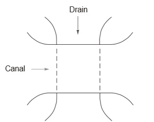
Fig. Canal taken over the drain in an aqueduct or a syphon aqueduct (line plan of crossing)
- Aqueduct: HFL of drain is sufficiently below bed level of canal and water flows freely under the action of gravity in drain, then the cross drainage work is known as aqueduct.
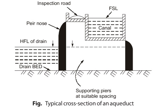
In aqueduct, canal water is taken across drainage in a trough supported on piers. In other words, it can be said that it is just like a bridge except that instead of carrying a road or railway, it carries a canal on its top.
- Syphon Aqueduct: If HFL of drain is higher than canal bed level and water passes through aqueduct barrels under syphonic action, then the cross-drainage work is known as syphon aqueduct.
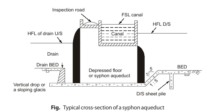
In syphon aqueduct, drain bed is generally depressed and provided with pucca floor. On upstream side, drainage bed is joined to pucca floor by either a vertical drop or a sloping glacis depending upon height of drop.
Super Passage and Canal Syphon
In these structures, drain is taken over canal such that canal runs below drain either freely or under syphonic pressure as shown in figure.
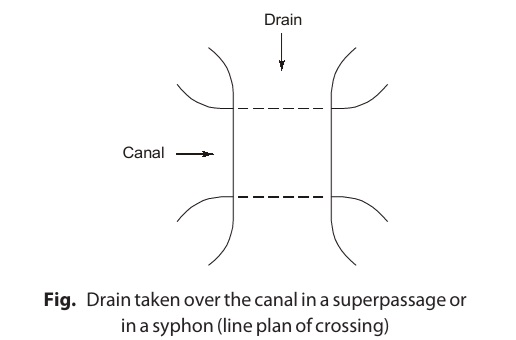
A. Super Passage:
If the FSL of canal is sufficiently below bottom of drain so that water flows freely under the action of gravity in canal, then the cross-drainage work is known as super passage.

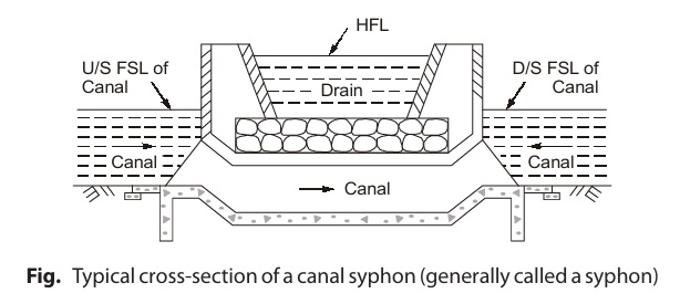
B. Canal Syphon or Syphon:
If FSL of canal is above bed level of drain and canal flows under syphonic action under the through, then the cross-drainage work is known as canal syphon canal syphon canal syphon canal syphon canal syphon. It is just the reverse of syphon aqueduct.
Level Crossing
A level crossing is provided when a large canal and a huge drainage (such as a stream or a river) approach each other at same level. In this type of structures, canal water and drain water are allowed to intermingle with each other.
Regulators are provided at
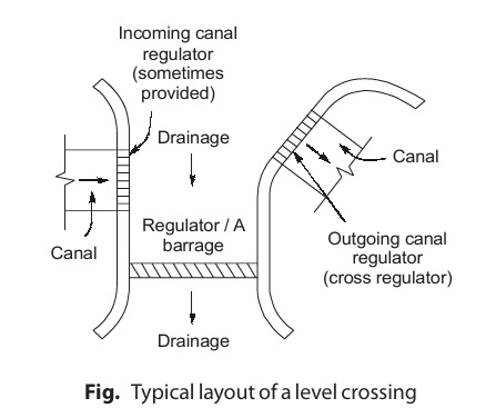
- Downstream side of drainage so as to control discharge passing through drain.
- Outgoing canal to control discharge in canal.
Sometimes, a regulator is also provided at end of incoming canal. This arrangement is generally provided when a huge sized canal crosses a large drain carrying a very high flood discharge but for a very short interval.
Distributary Head Regulators and Cross Regulators
Cross regulator and distributary head regulator are provided to regulate the supplies of the parent channel and off taking channel respectively. A cross regulator is provided on the main canal (or the parent canal) at the downstream of the off take to head up the water level and enable the off taking channel to draw the required supply. A distributary head regulator is provided at the head of the off taking channel (or distributary) to control the supplies entering the off taking channel.
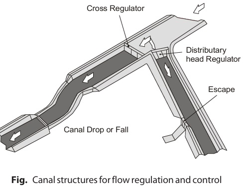
Functions of cross regulator are as following:
- To have effective regulation of the whole canal system.
- To help in feed the off taking channels by raising the water level of the upstream during the periods of low discharges in the parent channel.
- To help in closing the supply to the downstream of the parent channel for the purposes of repairs etc.
- To help in absorbing fluctuations in various section of the canal system and in preventing the possibilities of breaches in the tail reaches.
- To facilitates communication works (like bridges)
- To help in controlling discharge at an outfall of canal into another canal or lake.
Functions of distributary head regulator are as following:
- To regulates the supplies to the off taking channel from the parent channel.
- To serve as a meter for measuring the discharge entering into the offtaking canal.
- To regulates the entry of silt in the offtaking channel.
- To shuts off the supply when it is not needed in the off taking channel or when the off taking channel is required to be closed for repairs.
Types of Canal Escapes
Escapes are usually of the following types.
(a) Based on Structural Design
- Weir or Surface Escape: Weir or Surface Escape: These are weirs or flush escapes constructed either in masonry or
concrete with or without crest shutters which are capable of disposing off surplus water from the canal.
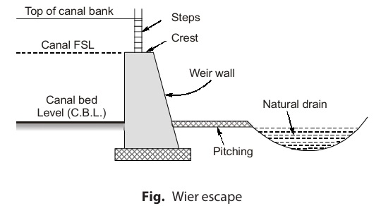
Weir type escapes acts as both surplus water escapes and tail water escapes.
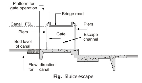
- Sluice Escapes: A sluice escape is a small regulator which is provided in the canal bank and has gates supported on piers. There are also called regulator escape. Sluice escapes acts both as surplus water escape and canal scouring escapes. These sluices can empty the canal quickly for repair and maintenance and also facilitates quick removal of sediment.
(b) Based on the Purpose
Escapes are usually of following types:
(i) Surplus Water Escape: These escapes are provided in the banks of the channel at intervals depending on the importance of the channel and in the vicinity of the drain or river for disposing excess water. Escape must be so located that surplus water is led through the shortest possible distance to a natural drain (i.e. we should have shortest possible escape channel) The channel leading surplus water from escape to natural drain is called escape channel or outfall channel. It can discharge the excess flow of the canal or even empty the entire canal flow through its gate controlled vents.
(ii) Canal Scouring Escapes: These escapes are provided only at the head reaches of the main canal, in the banks of channel. Usually, a cross regulator is provided across the channel just on the downstream side of location of escape.
(iii) Tail Escapes: These escapes are provided across the channels at the tail ends in case of irrigation channels which end in natural drain. Tail escapes are provided to maintain the required full supply level (F.S.L) at the tail end of the channel.
Types of Canal Outlets
Canal outlets can be classified mainly into three classes:
- Non modular outlets
- Semi-modular outlets
- Modular outlets
(a) Non-modular Outlets
Non-modular outlets are those outlets whose discharge depends on the difference of water levels (i.e. head) between the distributary and the water course. The discharge through non modular outlets varies widely with variations in the water level of either the distributary or the water course. Such an outlet is controlled by a shutter at its upstream end. Non modular outlets are very suitable for low head condition. Examples: Submerged pipe outlets and masonry sluices.
(b) Semi Modular Outlets
Semi modular outlets are those outlets whose discharge depends only on the water level in the distributary and is unaffected by the water level in the water course provided that a minimum working head required for working is available. Semi modular outlet is more suitable for achieving equitable distribution of water at all outlets of a distributary. Examples: Pipe outlet, Venturi flume.
(c) Modular Outlets
Modular outlets are those outlets whose discharge is independent of the difference of water levels in the distributary and the water course. These are called Rigid Modules Example: Gibb’s Module
<< Previous | Next >>
Must Read: What is Irrigation Engineering?
Dear Aspirants,
Your preparation for GATE, ESE, PSUs, and AE/JE is now smarter than ever — thanks to the MADE EASY YouTube channel.
This is not just a channel, but a complete strategy for success, where you get toppers strategies, PYQ–GTQ discussions, current affairs updates, and important job-related information, all delivered by the country’s best teachers and industry experts.
If you also want to stay one step ahead in the race to success, subscribe to MADE EASY on YouTube and stay connected with us on social media.
MADE EASY — where preparation happens with confidence.
MADE EASY is a well-organized institute, complete in all aspects, and provides quality guidance for both written and personality tests. MADE EASY has produced top-ranked students in ESE, GATE, and various public sector exams. The publishing team regularly writes exam-related blogs based on conversations with the faculty, helping students prepare effectively for their exams.
