Volumetric Mix
Volumetric Mix describes the relative volume proportions among the various constituent of bituminous mix.
A bitumen mix comprises of aggregate, bitumen and air voids. Aggregates present in mix comprises of coarse and fine particles. There are voids present in aggregates some of which contains bitumen and remaining voids are filled with air. Figure below represent a schematic diagram of various volume components of bituminous mix as a whole.
Various terms in phase diagram and specific gravities defined for bituminous mix are explained below:
1. Theoretical or Apparent specific gravity (Gt): It is the maximum specific gravity for a bitumenous mix because air is not considered in volume of mix while calculating this specific gravity
So, Theoretical specific gravity, Gt = Wmix / Volume of (mix-air voids)
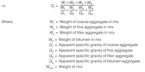
2. Bulk specific gravity of mix (Gm): It is specific gravity of mix in which air voids are also included in volume of mix.
Bulk specific gravity of mix, Gm = Wmix / Bulk volume of mix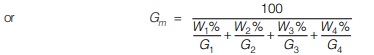
Here, bulk volume of mix can be calculated by two method.
3. Percent air void (VA)%
It is expressed as volume of air voids to total volume of mix.
It can be obtained as follows: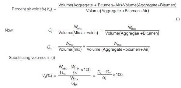
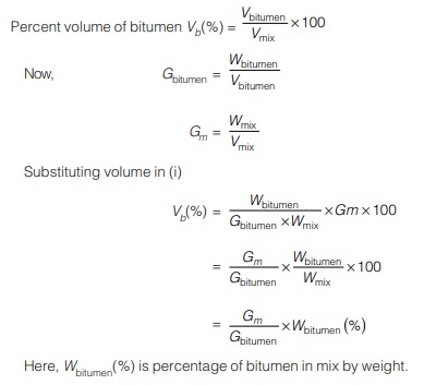
4. Percent volume of bitumen (Vb)%
It is expressed as volume of bitumen to total volume of mix.
It can be obtained as follows:
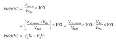
5. Void in mineral aggregate (VMA)
It is expressed as percent of total volume of voids (bitumen + air) to total volume of mix.
It can be obtained as shown below:
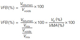
6. Voids Filled with bitumen (VFB)
It is expressed as percentage of volume of bitumen to total volume of voids.
It can be obtained as follows:
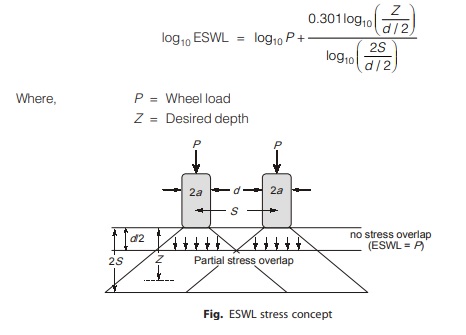
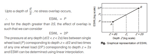
(c) Equivalent Single Wheel Load (ESWL)
- It is defined as load on the single tyre which will cause an equivalent magnitude of stress, strain, deflection etc. at a given location to that of multiple wheel load at the same location. To maintain the maximum wheel load within the specified limit, it is necessary to provide dual wheel assembly to the rear axles of road vehicles.The effect of dual wheel assembly is not equal to two times the load of any wheel. Equivalent single wheel load is calculated by using equal stress criteria. It is a semi-rational method, known as Boyd and Foster method, based on the following assumptions:
- Equivalency concept is based on equal stress
- Contact area is circular
- Influence angle is 45°
- Soil medium is elastic, homogenous and isotropic
- In a dual wheel load assembly, let ‘d’ is the clear gap between two wheel, ‘S’ be the spacing between center of the wheels and ‘a’ be the radius of the circular contact area of each wheelTherefore, S = d + 2aThe ESWL is given by:
Modified CBR-method
Initially, total number of commercial vehicles were considered for designing of flexible pavement using CBR method but now as per IRC-37: 2018, in modified CBR method, design traffic is defined in term of total number of cumulative standard axle loads which is calculated by an expression as given below: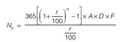
Ns = Number of cumulative standard axles to be catered during
the design period of ‘n’ years
A = Initial traffic (commercial vehicle per day) in year of completion of construction (directional traffic volume to be considered for divided carriageways, two way traffic volume may be considered for applying lateral distribution factors)
D = Lateral distribution factor
F = Vehicle damage factor
n = Design period, in years
r = Annual growth rate of commercial vehicles
Also, the traffic in year of completion of construction may be estimated by equation:![]()
Where, P = Number of commercial vehicle per day as per last count
x = Number of years between last count and year of completion of construction
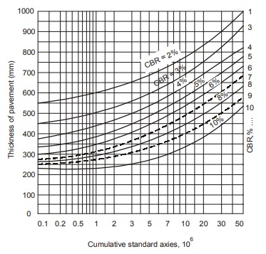
After calculating number of cumulative standard axle, total pavement thickness is determined using the design chart(IRC 37 : 2001) as given below.
Calculation of vehicle damage factor and lateral distribution factor
(a) Vehicle Damage Factor
It is defined as a equivalent number of standard axles per commercial vehicle. The vehicle damage factor is used to convert the number of commercial vehicles of different axle loads and axle configuration to the number of standard axle load repetitions.
The vehicle damage factor for any axle load is given as: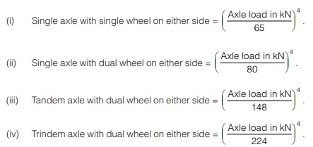
| IRC recommended values of VDF | ||
|---|---|---|
| Initial (two way) traffic volume in terms of number of commercial vehicle per day | Terrain | |
| Rolling/ plain | Hilly | |
|
0 – 150 |
1.7 | 0.6 |
|
150 – 1500 |
3.9 |
1.7 |
| > 1500 | 5.0 |
2.8 |
Triaxial Test Method
In 1910 L.A. Palmer and E.S. Barber proposed the design method based on Boussinesq’s displacement equation for homogenous elastic single layer. The expression for pavement thickness is given as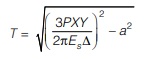
Where,
T = Pavement thickness in cm
P = Wheel load in kg
Es = Modulus of elasticity of subgrade from triaxial test results in kg/cm2
a = Radius of contact area in cm
∆ = Design deflection (taken equal to 0.25 cm)
X = Traffic coefficient
Y = Saturation coefficient
The recommended values of coefficients X and Y based on ADT of design traffic and rainfall are given in Table.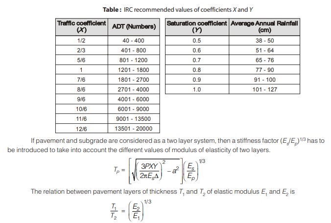
Burmister Method 
This method is based on young’s modulus of elasticity of different layer of pavement.
As flexible pavement composed of layers and elastic modulus of top most layer is maximum.
Eb > Esb > Es
Boussinesq’s analysis is a special case of Burmister’s layered system analysis. He considered
Eb = Esb = Es
Assumptions involved in Burmister’s analysis
(i) Materials in the pavement layers are isotropic, homogenous and elastic.
(ii) Pavement forms a stiffer reinforcing layer having modulus of elasticity higher than the underlying subgrade.
(iii) Surface layer is infinite in horizontal direction but finite in vertical direction.
(iv) Underlying layer is infinite in both the directions.
(v) The layers are in continuous contact.
Displacement equations given by Burmister are given below.
(i) For Flexible Plate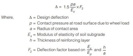
(ii) For Rigid Plate 
<< Previous | Next >>
Must Read: What is Highway Engineering?
Dear Aspirants,
Your preparation for GATE, ESE, PSUs, and AE/JE is now smarter than ever — thanks to the MADE EASY YouTube channel.
This is not just a channel, but a complete strategy for success, where you get toppers strategies, PYQ–GTQ discussions, current affairs updates, and important job-related information, all delivered by the country’s best teachers and industry experts.
If you also want to stay one step ahead in the race to success, subscribe to MADE EASY on YouTube and stay connected with us on social media.
MADE EASY — where preparation happens with confidence.
MADE EASY is a well-organized institute, complete in all aspects, and provides quality guidance for both written and personality tests. MADE EASY has produced top-ranked students in ESE, GATE, and various public sector exams. The publishing team regularly writes exam-related blogs based on conversations with the faculty, helping students prepare effectively for their exams.
