Factors Affecting Geometric Design
There are certain basic design controls and criteria which govern the geometric features of a highway.
- Topography
- Design speed
- Road user characteristics
- Vehicle characteristics
- Traffic (its volume, directional distribution and composition including the future estimates)
- Traffic capacity
- Environmental considerations
- Economy in construction, maintenance and operation of vehicles
Camber or Cross Slope
| Camber for different road surfaces | |
|---|---|
| Types of road surface Range of camber |
Heavy Rainfall to light rainfall |
| Cement concrete and high type bituminous surface | 1 to 50 (2.0%) to 1 in 60 (1.7%) |
| Thin bituminous surface | 1 to 40 (2.5%) to 1 in 50 (2.0%) |
| Water bound macadam and gravel pavement | 1 to 33 (3%) to 1 in 40 (2.5%) |
| Earth | 1 to 25 (4.1%) to 1 in 33 (3.0%) |
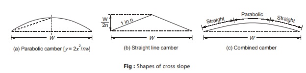
Transverse slope provided to the road to drain off rain water from road surface is known as camber. It is measured in 1 in ‘n’ or n% (e.g. 1 in 50 or 2%). Main advantage of providing camber are quick drying of pavement which in turn increases safety and subgrade protection by drainage.
Requirement of camber of a pavement depends upon:
- Type of pavement surface
- The amount of rainfall
Camber may be provided in the shape of parabolic, elliptic or straight line shape. For cement concrete pavement, straight line camber is provided while parabolic and elliptic shape are preferred for fast moving vehicles because they require frequent crossing of crown line during overtaking operation.
The camber of shoulder should be atleast 0.5% steeper than the cross slope of adjoining pavement, subjected to a minimum of 3.0% and a maximum value of 5.0% for earth shoulder.
Disadvantages of excessive camber are:
- Transverse tilt of vehicle and discomfort
- Formation of cross ruts or depression
- Tendency of the vehicle to move along the centre line
Stopping Sight Distance
Stopping sight distance is the minimum distance over which the driver travelling at design speed can apply brakes and bring the vehicle to stop position safely without having collision with any other obstruction. It is also known as minimum sight distance or non passing sight distance. Stopping sight distance should be provided throughout the length of all roads.
Stopping sight distance composed of two components: (i.e. lag distance and braking distance)
(i) Lag Distance (d): It is the distance travelled by the vehicle in total reaction time, if v is the design speed in m/s and t is the total reaction time (in sec). Value of ‘t ’ is taken as 2.5 seconds in case of stopping sight distance.
Now, lag distance (d ) = vt metres
If V is design speed in kmph and t in seconds, then
d = 0.278 Vt metres
(ii) Braking Distance (l): It is the distance travelled by vehicle after the application of brakes. It is obtained by equating the work done in stopping the vehicle and kinetic energy stored in the vehicle. Let us consider, F is the maximum frictional force developed and l is the braking distance, then the workdone against friction force in stopping the vehicle will be F l.
where, frictional force, F = fW
where,‘W ’ is the total weight of vehicle and ‘f ’ is the coefficient of friction
So, workdone in stopping the vehicle = fWl
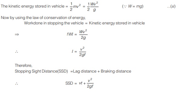
where, ‘v’ is design speed in m/s, ‘g’ is the acceleration due to gravity in m/s2, ‘t’ is the total reaction time in sec and ‘f’ is coefficient of friction.
Overtaking Sight Distance (OSD)
Overtaking is a necessary operation because all the vehicles do not travel with a uniform speed. Overtaking is only possible when driver has sufficient sight distance to complete the whole operation.
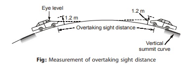
Overtaking sight distance (OSD) is the minimum distance visible to the driver of a vehicle who is intending to overtake the slow moving vehicle ahead safely against the traffic of opposite direction. It is measured along the centre line of road over which driver with his eye level 1.2 m above the pavement surface can see the top of an object of height 1.2 m above the road surface as shown in Figure.
Factors affecting the overtaking sight distance:
- Speed of overtaking vehicles, overtaken vehicle and vehicle coming from opposite direction, if any (the minimum spacing depends on the speeds)
- The spacing between overtaking and overtaken vehicle
- Skill and reaction time of driver
- Rate of acceleration of overtaking vehicle
- Gradient of the road
Analysis of Overtaking Sight Distance
Let us suppose, Vehicle A = Travelling at the design speed of highway
Vehicle B = Slow moving vehicle which is going to be overtaken by vehicle A
Vehicle C = Travelling in the opposite direction of vehicle A and B
The whole process of overtaking is split into three parts d1, d2 and d3.
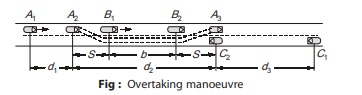
Where, d1 = Distance travelled by overtaking vehicle A during the reaction time t sec.
d2 = Distance travelled by the vehicle A during the actual overtaking operation in time T seconds.
d3 = Distance travelled by the vehicle C coming from the opposite direction.
Vb = Speed of the slow moving vehicle (in kmph)
The following assumptions are made during calculation of d1 d2 and d3.
- The vehicle A is forced to reduce its speed to the speed of slow moving vehicle (Vb).
- Spacing between vehicle A and vehicle B is s, till there is an opportunity for safe overtaking operation and distance travelled by vehicle A during this reaction time is d1.
Now ‘d1’ is the distance travelled by the vehicle A in the reaction time, which is given as
d1 = vbt metres
Here, value of total reaction time (t) is taken as 2.0 seconds.
and, vb = Speed of slow moving vehicle in m/s
Spacing between the vehicle A and B just before the starting of overtaking operation (i.e. at position A2 and B1) when both the vehicles moving with the speed of vb m/s is given by an empirical formula
S = 0.7 vb + length of vehicle
Generally , length of vehicle considered is 6 m
S = 0.7 vb + 6 metres …[vb in m/s]
or S = 0.2 vb + 6 metres …[vb in kmph]
Let, ‘b’ is the distance travelled by vehicle B in the complete overtaking operation time, ‘T ’ sec.
b = vbT metres
d2 = b + 2S metres …(i)
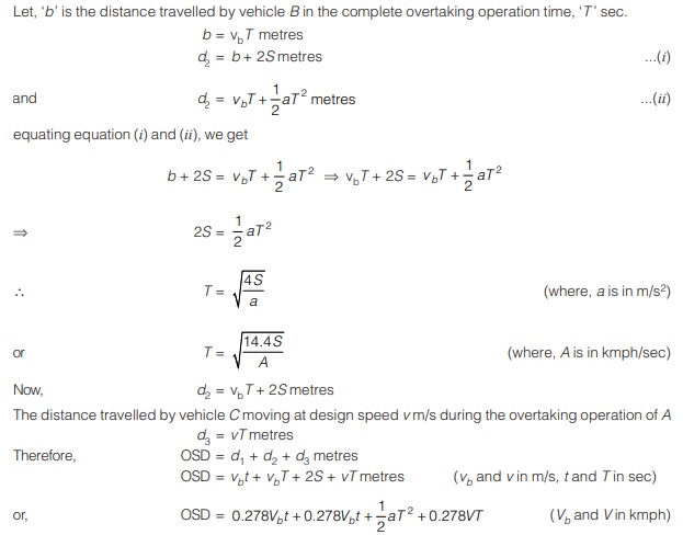
The values of overtaking sight distance recommended by IRC are given in Table given below.
| Overtaking sight distance | ||||||
|---|---|---|---|---|---|---|
| Speed (kmph) | 40 | 50 | 60 | 65 | 80 | 100 |
| Safe Overtaking Sight Distance (metres) | 165 | 235 | 300 | 340 | 470 | 640 |
<< Previous | Next >>
Must Read: What is Highway Engineering?
Dear Aspirants,
Your preparation for GATE, ESE, PSUs, and AE/JE is now smarter than ever — thanks to the MADE EASY YouTube channel.
This is not just a channel, but a complete strategy for success, where you get toppers strategies, PYQ–GTQ discussions, current affairs updates, and important job-related information, all delivered by the country’s best teachers and industry experts.
If you also want to stay one step ahead in the race to success, subscribe to MADE EASY on YouTube and stay connected with us on social media.
MADE EASY — where preparation happens with confidence.
MADE EASY is a well-organized institute, complete in all aspects, and provides quality guidance for both written and personality tests. MADE EASY has produced top-ranked students in ESE, GATE, and various public sector exams. The publishing team regularly writes exam-related blogs based on conversations with the faculty, helping students prepare effectively for their exams.
