Various Connections in Pipelines
Series Connections
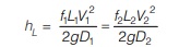
If a pipe line connecting two reservoirs is made up of several pipes of different diameter D1, D2, D3 ,… etc, and length L1, L2, L3,… etc. all connected in series (i.e. end to end) the flow rate through the entire system remains constant regardless of the diameters of individual pipes in the system and total head loss in this case in equal to sum of the head loss in individual pipes in the system.
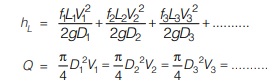
From Equations (i) and (ii) we can solve problems of pipelines in series. There are two types of problems as given:
Given discharge Q ; to determine hL 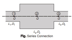
- Since discharge, diameter and length of the pipes are known, the Reynolds number can be computed and values of f1, f2, f3 etc. can be found from Moody’s chart.
- These values can be substituted in Equations (i) and (ii) to get discharge.
Given hL; to determine discharge Q
- Assume f1, f2 and f3 (These can be assumed equal for simplicity).
- Compute V, Re, ∈/D (relative roughness) and then calculate ‘f ’ (Moody’s chart can be used).
- Repeat the process to get accurate results.
Equivalent Pipe
- When a compound pipeline consisting of several pipes of varying diameters and lengths, is replaced by a pipe of uniform diameter having same material, it is called equivalent pipeline.
- The uniform diameter of equivalent pipe is known as equivalent diameter of the compound pipe.
- If L1, L2, L3, etc be the length and D1, D2, D3… etc be the diameter of the different pipes of a compound pipe line, and if D is the diameter and Le is the length of the equivalent pipe, then
![]()
The above Equation is called Dupuit’s Equation.
Parallel Connections
- When a main pipeline divides into two or more parallel pipes which again join together downstream and continue as a main pipeline, the pipes are said to be in parallel connection.
- If pipe divides into two parallel pipes then rate of discharge in the main line is equal to the sum of discharges in each parallel pipe;
Q = Q1 + Q2 …(iii) - Since end condition of parallel pipes are same hence loss of energy through each pipe will be the same
- Using Equations (iii) and (iv) we can solve problems of pipes in parallel.
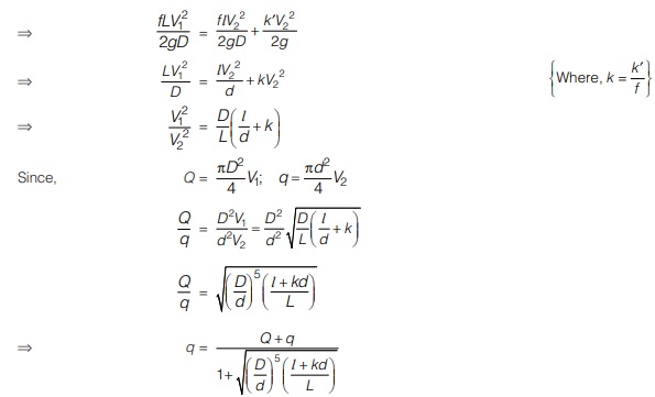
FLOW THROUGH A BY-PASS
- A by-pass is a diversion provided for main pipeline in which mainline is tapped at some point by a smaller pipe which later returns to the main at another point as shown. Head loss in mainline between sections (1) and (2)
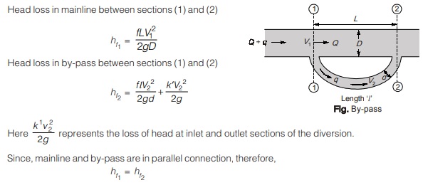
A by-pass may be used for measuring the discharge passing through the city water supply mains which are usually of very big size and for these other discharge measuring devices are not available.
<< Previous | Next >>
Must Read: What is Fluid Mechanics?
Dear Aspirants,
Your preparation for GATE, ESE, PSUs, and AE/JE is now smarter than ever — thanks to the MADE EASY YouTube channel.
This is not just a channel, but a complete strategy for success, where you get toppers strategies, PYQ–GTQ discussions, current affairs updates, and important job-related information, all delivered by the country’s best teachers and industry experts.
If you also want to stay one step ahead in the race to success, subscribe to MADE EASY on YouTube and stay connected with us on social media.
MADE EASY — where preparation happens with confidence.
MADE EASY is a well-organized institute, complete in all aspects, and provides quality guidance for both written and personality tests. MADE EASY has produced top-ranked students in ESE, GATE, and various public sector exams. The publishing team regularly writes exam-related blogs based on conversations with the faculty, helping students prepare effectively for their exams.
