Pressure Diagram or Prism
- A pressure diagram or prism is a graphical representation of the variation of pressure intensity over a plane
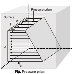 surface.
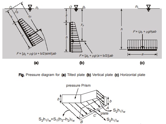
 - Total hydrostatic force as well as centre of pressure for a plane surface can be determined by drawing a pressure diagram.
- Net force on plate is equal to volume of the pressure prism.
- Point of application of resultant force is at centre of gravity (C.G.) of the prism projected on the plate.
- It can be drawn for a plane surface in any orientation.
NOTE: Pressure diagram approach is useful when the section is rectangular or square.
If the plate is completely submerged in one liquid only (even if there is other type of liquid present above the plate),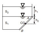 the pressure force on plate will be simply, pressure at the CG of plate multiplied by area of plate.
Force on AC = Pressure at the C.G. of AC multiplied by area of AC
Force on CB = Pressure at the C.G. of CB multiplied by area of C.B.
Point of application of resultant force can be calculated as the C.G. of pressure prism on AB projected on AB.
Force on Plate AB = (S2γwh1 + S1γwh2)A,
A = Area of plate
<< Previous | Next >>
Must Read: What is Fluid Mechanics?
Dear Aspirants,
Your preparation for GATE, ESE, PSUs, and AE/JE is now smarter than ever — thanks to the MADE EASY YouTube channel.
This is not just a channel, but a complete strategy for success, where you get toppers strategies, PYQ–GTQ discussions, current affairs updates, and important job-related information, all delivered by the country’s best teachers and industry experts.
If you also want to stay one step ahead in the race to success, subscribe to MADE EASY on YouTube and stay connected with us on social media.
MADE EASY — where preparation happens with confidence.
MADE EASY is a well-organized institute, complete in all aspects, and provides quality guidance for both written and personality tests. MADE EASY has produced top-ranked students in ESE, GATE, and various public sector exams. The publishing team regularly writes exam-related blogs based on conversations with the faculty, helping students prepare effectively for their exams.
