Heads of a Turbine
In hydroelectric power plant, head is the height difference between where the water enters into a hydroelectric power plant to where it leave it.
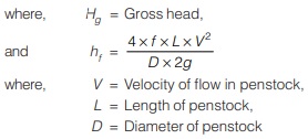
Gross Head
- The difference between the head race level and tail race level when no water is flowing is known as gross head. It is denoted by Hg.
- It does not remain constant as both the levels (tail race level and head race level) changes with time.
Net Head
- It is also called effective head and is defined as the head available at the inlet of the turbine.
- When water is flowing from head race to the turbine, a loss of head due to friction between the water and penstocks occurs. Though there are other losses also such as loss due to bend, pipe fittings, loss at the entrance of penstock etc., yet they are having small magnitude as compared to head loss due to friction.
- If ‘hf’ is the head loss due to friction between penstocks and water, then net head on turbine is given by
H = Hg – hf
PELTON TURBINE
- Pelton turbine is a tangential flow impulse turbine having high head low discharge turbine.
- Water coming from the nozzle impinges on the bucket attached to the shaft of turbine which causes force on bucket. The force creates torque necessary for rotation for shaft.
- All the head is converted to kinetic head before the jet impinges on the bucket.
- Water is always in contact with atmosphere. Hence throughout its operation water is at atmospheric pressure.
Components of Pelton turbine
The components of Pelton turbine are as follows:
Nozzle and Governor 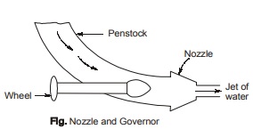
- To control the discharge passing through the nozzle and striking the bucket, a spear is provided which can move forward or backward with the help of governor in order to decrease or increase the flow through nozzle respectively.
- Governor and spear helps in meeting the variable demand of power and thus maintains the speed of the wheel constant even when head varies.
- When speed of the wheel increases, the spear is pushed into the nozzle thereby reducing the quantity of water striking the bucket. If the speed of the wheel falls, the spear is withdrawn back allowing a greater quantity of water to pass through nozzle.
- The process of maintaining constant speed in respective of change in load is called governing of hydraulic turbine.
Runner or Buckets 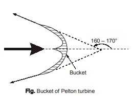
- Pelton turbine consists buckets mounted on the runner. Each bucket is divided into two parts by a splitter which has a sharp edge at the centre giving the shape of a double hemispherical cup.
- The splitter divide the jet without shock into two parts moving sideways in opposite direction.
- The advantage of having double cup shaped buckets is that the axial thrust neutralizes each other.
- The buckets are shaped so that the jet gets deflected through 160° – 170°.
Casing
- The casing of Pelton turbine has no hydraulic function to perform. It is used just to avoid the splashing of water and safe guard against accidents.
Breaking Jet
- It is a small nozzle, which is used to stop closing of nozzle, by directing a jet of water on the back of vanes.
- Least diameter of the braking jet is 0.6 times least diameter of main jet.
<< Previous | Next >>
Must Read: What is Fluid Mechanics?
Dear Aspirants,
Your preparation for GATE, ESE, PSUs, and AE/JE is now smarter than ever — thanks to the MADE EASY YouTube channel.
This is not just a channel, but a complete strategy for success, where you get toppers strategies, PYQ–GTQ discussions, current affairs updates, and important job-related information, all delivered by the country’s best teachers and industry experts.
If you also want to stay one step ahead in the race to success, subscribe to MADE EASY on YouTube and stay connected with us on social media.
MADE EASY — where preparation happens with confidence.
MADE EASY is a well-organized institute, complete in all aspects, and provides quality guidance for both written and personality tests. MADE EASY has produced top-ranked students in ESE, GATE, and various public sector exams. The publishing team regularly writes exam-related blogs based on conversations with the faculty, helping students prepare effectively for their exams.
